Secondary battery

a secondary battery and battery case technology, applied in the field of secondary batteries, can solve the problems of increasing affecting the safety of secondary batteries, and causing greater damage than conventional batteries, and achieve the effects of high energy density, high capacity and high safety

Inactive Publication Date: 2015-06-23
SHIN KOBE ELECTRIC MASCH CO LTD
View PDF21 Cites 0 Cited by
  • Summary
  • Abstract
  • Description
  • Claims
  • Application Information

AI Technical Summary

Benefits of technology

[0017]An object of the present invention is to provide a secondary battery with a large capacity and a high energy density that excels in safety by reliably discharging gas from the battery when a safety valve is actuated or operated.
[0018]A secondary battery according to the present invention comprises an electrode group and a battery case. The electrode group includes one or more negative electrodes each having a negative current collecting member and a negative active material held on the negative current collecting member, one or more positive electrodes each having a positive current collecting member and a positive active material held on the positive current collecting member, and a separator holding an electrolyte. The one or more negative electrodes and the one or more positive electrodes are alternately layered via the separator. The battery case includes a case body having an opening portion and receiving the electrode group and a lid plate closing the opening portion. The secondary battery according to the present invention also includes: a negative output terminal member provided with the lid plate and electrically connected to the one or more negative electrodes; a positive output terminal member provided with the lid plate and electrically connected to the one or more positive electrodes; and a safety valve. The safety valve is provided at the lid plate at a position between the negative output terminal member and the positive output terminal member, and includes an opening area to be opened when the internal pressure of the battery case rises to a predetermined pressure or higher. The safety valve is disposed to partially overlap with an imaginary center line passing through the center between the negative output terminal member and the positive output terminal member and extending along a plate surface of the lid plate to divide the lid plate into two halves. In the present invention, the safety valve, the negative output terminal member, and the positive output terminal member are configured to satisfy the following two conditions. A first condition is that the minimum distance from the imaginary center line to respective end edges of the negative output terminal member and the positive output terminal member on the side of the safety valve is equal to or less than the minimum distance from the imaginary center line to the outermost end edge of the safety valve. A second condition is that a shadow area obtained by projecting the opening area of the safety valve onto an imaginary plane extending along the plate surface of the lid plate does not overlap with respective shadow areas obtained by projecting the negative output terminal member and the positive output terminal member onto the imaginary plane. With this configuration, the shadow area of the opening area of the safety valve does not overlap with the respective shadow areas of the positive output terminal member and the negative output terminal member even if such output terminal members are increased in size. Therefore, a passage for releasing gas from the electrode group to the safety valve is secured to smoothly discharge gas produced during an abnormality to the outside of the battery case. As a result, it is possible to provide a battery structure with a large capacity that ensures enhanced safety.
[0019]Preferably, the safety valve is disposed in the lid plate which is located in a direction perpendicular to a layering direction in which the positive electrodes and the negative electrodes in the electrode group are layered. This allows gas produced between the positive current collecting member and the negative current collecting member of the electrode group to pass through a space between the positive current collecting member and the negative current collecting member to be discharged in the direction perpendicular to the layering direction. As a result, it is possible to provide a battery structure that ensures enhanced safety by smoothly discharging gas.
[0020]The lid plate may have a rectangular profile, and the safety valve may have a circular profile. In such a case, the safety valve is preferably disposed with its center located at the intersection of the two diagonal lines of the lid plate. An electrical connection tab may be formed at an end portion of the positive current collecting member facing the lid plate. An electrical connection tab may be formed at an end portion of the negative current collecting member facing the lid plate. In such a case, the electrical connection tab of the positive current collecting member and the positive output terminal member may be connected to each other at a position outside the profile of the safety valve. Also, the electrical connection tab of the negative current collecting member and the negative output terminal member may be connected to each other at a position outside the profile of the safety valve. This allows the safety valve to be disposed at the center of the lid plate, which increases the profile of the safety valve. With the tabs and the output terminal members connected to each other at positions which are between the outer periphery of the lid plate and the profile of the safety valve, the positions of connection between the tabs and the output terminal members do not overlap with the safety valve, to secure a passage for discharging gas from the electrode group to the safety valve. As a result, it is possible to provide a battery structure with a large capacity that ensures enhanced safety by smoothly discharging gas produced during an abnormality to the outside of the battery case.
[0021]The electrical connection tab of the positive current collecting member and the positive output terminal member may be connected to each other at positions along two imaginary lines, in three imaginary lines dividing the plate surface of the lid plate into four equal quarters in the layering direction of the electrode group, excluding the center imaginary line in the three imaginary lines. The electrical connection tab of the negative current collecting member and the negative output terminal member may also be connected to each other at positions along the two imaginary lines. With this configuration, it is not necessary to make the tabs longer than necessary. The positive output terminal member and the negative output terminal member may be disposed symmetrically to each other with respect to the imaginary center line. In this case, the safety valve may be a circular metal foil provided with a groove pattern formed to open in a surface of the safety valve not facing the electrode group. The safety valve may also be a circular metal foil provided with a groove pattern formed to entirely open the opening area of the safety valve when the safety valve is in operation, in which case the effect of the present invention is enhanced.
[0022]Further, the safety valve may be a circular metal foil formed with a groove pattern. The groove pattern may be configured to have a portion passing through the center of the safety valve and an arcuate portion extending along the outer peripheral portion of the safety valve. The groove pattern may have a continuous unicursal design with no intersection. With the groove pattern having a portion passing through the center of the safety valve, it is possible to reduce fluctuations in cracking pressure, at which the safety valve is actuated by the pressure of gas produced during an abnormality. In addition, with the groove pattern having an arcuate portion extending along the outer periphery of the safety valve, it is possible to increase the opening diameter of the safety valve for its circumferential length. Further, with the groove pattern having a continuous unicursal design, it is possible to provide a battery structure with a large capacity and enhanced safety in which a crack in the groove pattern is smoothly propagated and in which fragments of the safety valve are not scattered by the gas discharge pressure. In this case, it is desirable that the groove pattern should have a shape generally corresponding to the shape of an alphabetic letter “s” or “e” or a swirling shape. However, it is apparent that any shape similar to such shapes provides the same effect to a greater or lesser degree.

Problems solved by technology

In addition to increasing the performance of the secondary batteries, increasing the safety of the secondary batteries is also an important issue.
If a rupture, an ignition, or the like occurs in batteries with a high energy density and a large capacity because of wrong use such as overcharging or a short circuit due to mixing of foreign matter, greater damage may be caused compared to the conventional batteries.
If the area of the safety valve is too small for the battery capacity, the amount of gas to be discharged to the outside of the battery case is small for the amount of generated gas.
Therefore, the internal pressure of the battery case may not stop rising even if the safety valve is actuated, which may lead to a breakage of the battery case itself.
Thus, increasing both the capacity and the energy density of a battery involves contradictory requirements for the size of the safety valve and the components to be energized such as the terminal members.
In the secondary battery disclosed in Japanese Patent Application Publication No. 2002-8616, however, no consideration is given to the geometry of the components to be energized such as the output terminal members and the tabs connected to the output terminal members, and no solution is proposed to the issue that generation of heat from the components to be energized such as the terminals and the tabs due to an increase in battery capacity should be suppressed.
Therefore, increasing the size of the safety valve and increasing the width of the output terminal members and the tabs along with an increase in battery capacity may result in the tabs and the output terminal members being extended to a location directly below the safety valve, which may hinder smooth discharge of generated gas during an abnormality.
Meanwhile, if the safety valve is disposed on a side surface of the battery case to allow a smooth flow of gas produced during an abnormality as in the secondary battery disclosed in Japanese Patent No. 3573295, it is necessary to form a hole or the like in a portion of the battery case other than the lid plate on which the positive output terminal member and the negative output terminal member are disposed, which increases the cost.
Therefore, it is necessary to provide a free space around two wall surfaces of the battery case, which significantly restricts installation of the battery or the like compared to the case where the safety valve and the output terminal members are disposed on the same wall surface.
Therefore, the safety valves may not be disposed at the center of an end portion of the battery case.
In addition, the size of each safety valve is limited to a value obtained by subtracting the radius of the electrode column from the radius of the cylindrical battery case or less.
Therefore, it is difficult to increase the diameter of the safety valves if the size of the electrode column is increased.
Moreover, the output terminals are disposed at both ends of the battery case, which requires a large volume of space for elements other than the power generating elements.
Thus, the energy density may not be enhanced compared to the case where the output terminals are provided on an identical wall surface of the battery case.
Thus, it has been difficult to increase the size of the safety valve in a battery with a large capacity and a high energy density and with a layered structure in which the output terminal members and the safety valve are provided in the lid plate of the battery case.

Method used


Image

  • Secondary battery
  • Secondary battery
  • Secondary battery

Examples


first embodiment

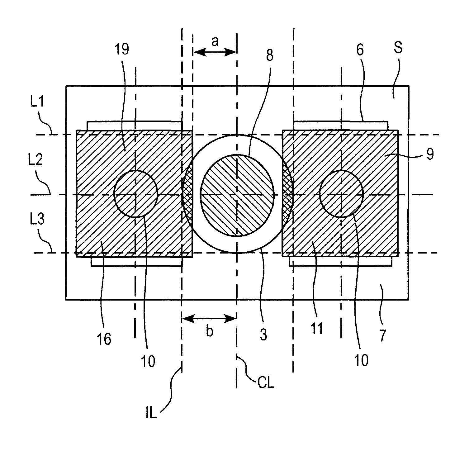
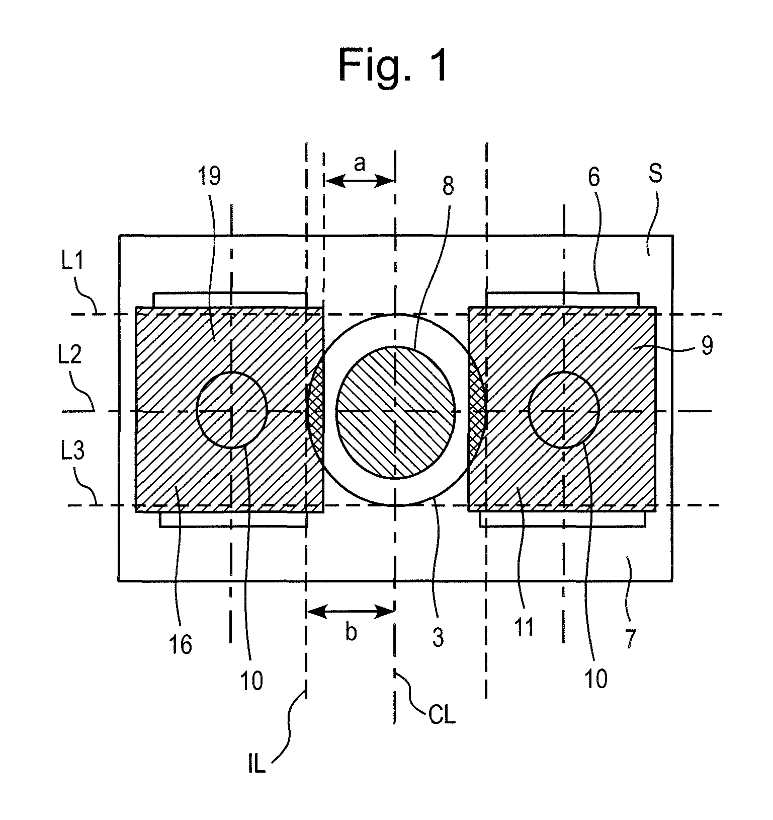
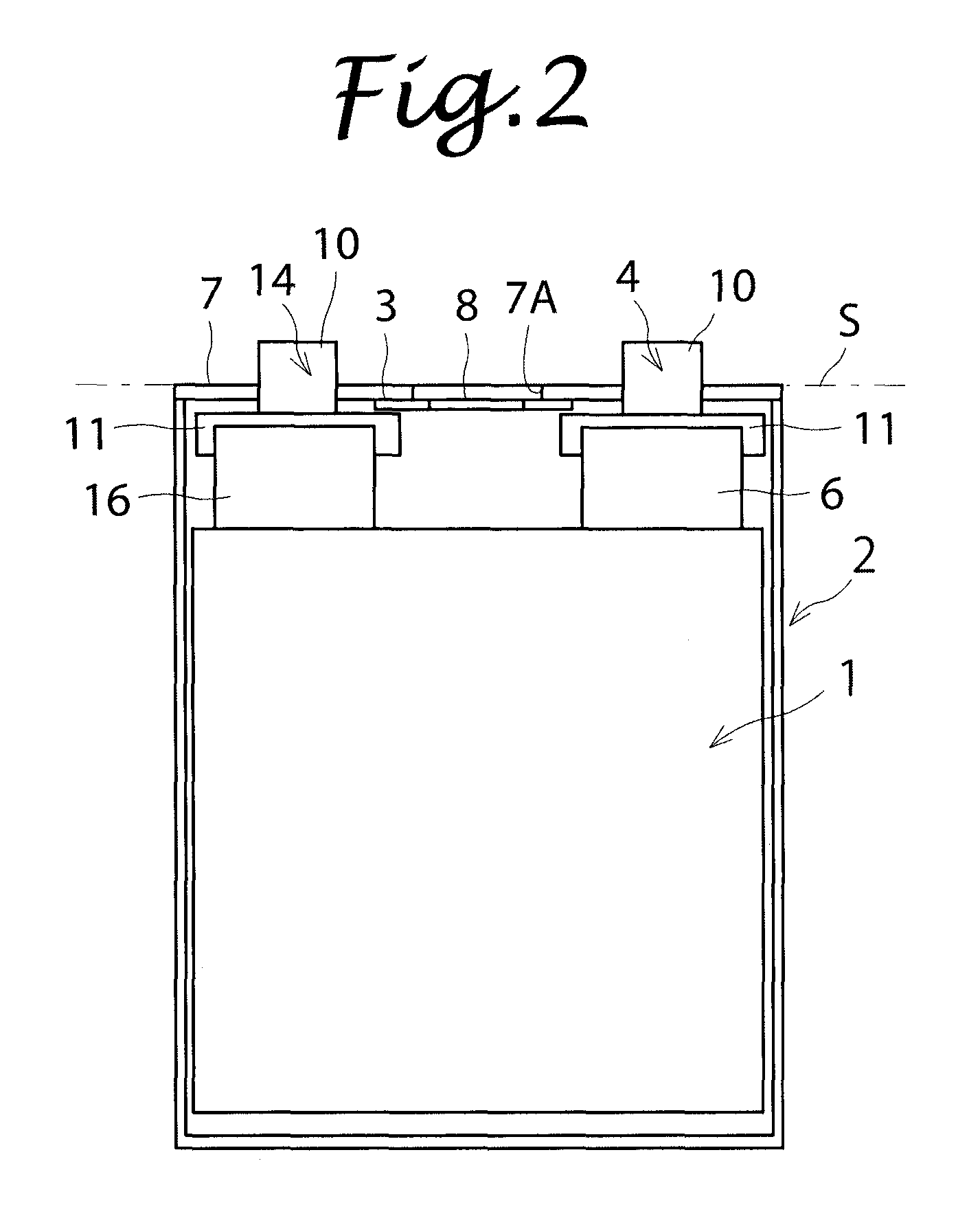
[0032]FIG. 1 is a projected view of a battery according to an embodiment of the present invention as viewed from the direction where a lid plate cab be seen. FIG. 2 is a transparent view of the battery of FIG. 1 as viewed from the direction where a side surface can be seen. A layered lithium-ion secondary battery with a battery capacity of 200 Ah is shown.

[0033]As shown in FIG. 2, an electrode group 1 includes a negative electrode having a rectangular negative current collecting member (copper) and a negative active material layer held on a surface of the negative current collecting member, a separator holding an electrolyte, and a positive electrode having a rectangular positive current collecting member (aluminum) and a positive active material layer held on a surface of the positive current collecting member. The positive electrode and the negative electrode are alternately layered via the separator. The dimension, such as the width, of the electrode group 1 and the number of pos...

second embodiment

[0041]FIG. 3 is a projected plan view of a battery according to a second embodiment of the present invention as viewed from above a lid plate 7′. The secondary battery according to the second embodiment is a lithium-ion secondary battery of a layered structure and with a capacity of 250 Ah which is 1.25 times larger than that of the battery according to the first embodiment. The capacity density has been improved by improving the positive and negative active material layers. The dimensions of the lid plate 7′ are the same as the lid plate 7 according to the first embodiment. In each of a positive output terminal member 4′ and a negative output terminal member 14′, a portion of a terminal base portion 11′ around a terminal portion 10′, which is a terminal for external connection that stands up vertically with respect to the lid plate 7′, is dented or curved toward the terminal portion 10′. A shadow area 8′ obtained by projecting the opening area of a safety valve 3′ in operation onto...


PUM

PropertyMeasurementUnit
battery capacityaaaaaaaaaa
internal pressureaaaaaaaaaa
pressureaaaaaaaaaa

Abstract

A safety valve is disposed to cover at least a portion of the center line of the lid plate between the pair of terminals for the positive electrode and the negative electrode. The distance from the center line of the lid plate to end portions of the components to be energized on the safety valve side is equal to or less than the distance from the center line of the lid plate to the outermost circumference of the safety valve. The shadow area obtained by projecting an opening portion of the safety valve in operation onto the plane of the lid plate does not overlap with the respective shadow areas obtained by projecting the electrically connected components, such as the external output terminals for the positive electrode and the negative electrode, onto the plane of the lid plate.

Description

BACKGROUND OF THE INVENTION[0001]1. Field of the Invention[0002]The present invention relates to a secondary battery having a safety valve.[0003]2. Description of the Related Art[0004]In recent years, in consideration of environmental issues, secondary batteries represented by lithium-ion batteries have been applied not only to mobile objects such as hybrid electric vehicles (HEVs), electric vehicles (EVs), forklifts, and excavators but also to industrial purposes such as uninterruptible power supplies (UPSs) and storages of electric power generated by solar power generation. As the usage of the secondary batteries is spread, it is sought to increase the capacity and the energy density of the secondary batteries.[0005]In addition to increasing the performance of the secondary batteries, increasing the safety of the secondary batteries is also an important issue. Examples of the secondary batteries include nickel-cadmium batteries, nickel-hydrogen batteries, and lithium-ion batteries...

Claims


Application Information

Patent Timeline
Patent Type & Authority Patents(United States)
IPC IPC(8): H01M2/12H01M2/04H01M10/0525H01M50/147
CPCH01M2/043H01M2/1241H01M10/0525Y02T10/7011Y02E60/10H01M50/147H01M50/3425Y02P70/50H01M2220/20H01M50/543H01M50/103Y02T10/70
Inventor TANAKA, AKIRASHINTO, MURASHIHOSHINO, KEIJIKAMEI, HIROSHI
Owner SHIN KOBE ELECTRIC MASCH CO LTD
Why Eureka
Try Eureka