A dual-component laser bonding device
A joining device and laser technology, applied in the direction of laser welding equipment, welding equipment, welding/welding/cutting items, etc., to achieve the effect of stable welding and high-speed welding
- Summary
- Abstract
- Description
- Claims
- Application Information
AI Technical Summary
Problems solved by technology
Method used
Image
Examples
Embodiment 1
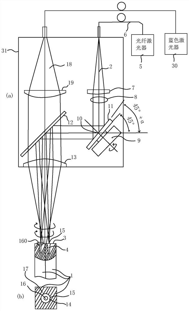
[0029] figure 1 (a) is a side view of the laser bonding apparatus and bonding method of two members of Example 1, figure 1 (b) is a plan view of the end faces of the two members viewed from the laser-irradiated upper surface.
[0030] The high-brightness fiber laser 2 that produces a keyhole on the machined surface 3 is emitted from the fiber laser 5 through the fiber 6 , and the collimated laser 8 is obtained through the collimating lens 7 .
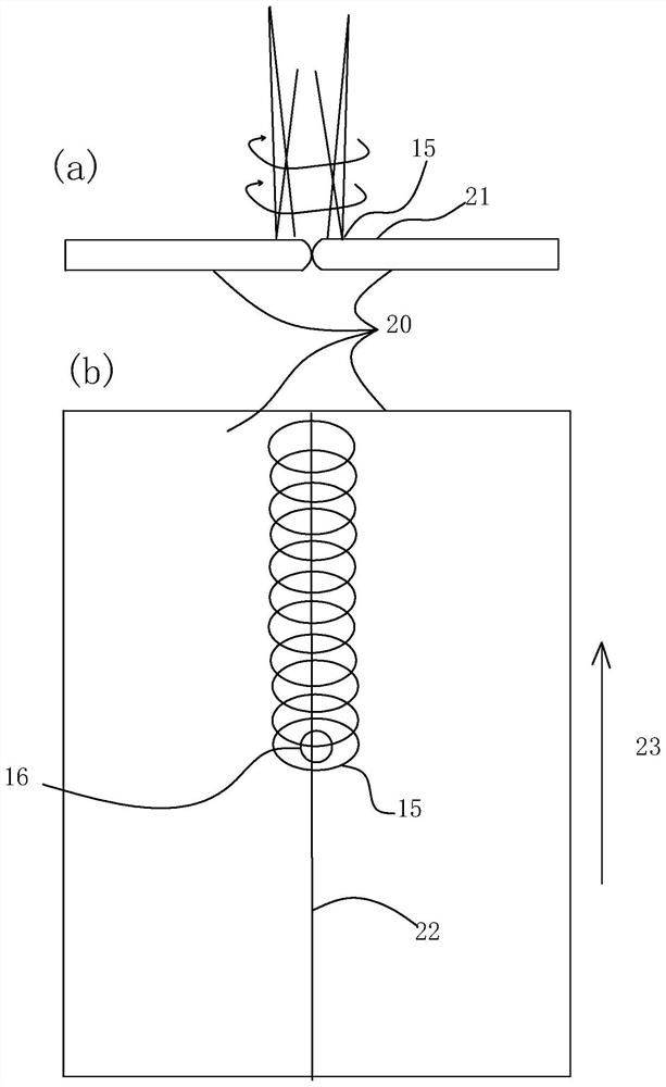
[0031] The collimated laser light 8 is reflected to approximately 90 degrees by a circular mirror 11 having a sloped shape fixed to the rotary motor 9 at the position of the rotation center of gravity 1 , and then reflected by the mirror 12 and condensed by a condenser lens 13 . The mirror 11 is mounted at an angle of 45°+α slightly larger than 45°, and is obtained by rotating at a high speed on the machined surface 3 with an angle of 45°+α. figure 1 The bonding center 14 shown in (b) is a laser focal point 15 that rotates in a cir...
Embodiment 2
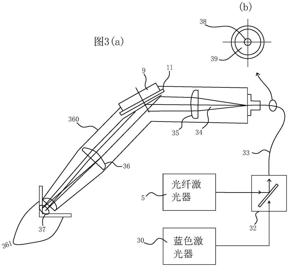
[0039] image 3 (a) shows that in Example 1, the fiber laser 2 and the blue laser 18 are wavelength-division-multiplexed in the laser output unit 31, and after wavelength-division multiplexing by the fiber-type wavelength division multiplexer 32, image 3 The core portion 38 of the double-clad process fiber 33 shown in (b) transmits fiber laser light through the cladding 39 , transmits blue laser light through the cladding 39 , and emits dual-wavelength laser light 34 . In addition, the description of the part which overlaps with Example 1 is abbreviate|omitted.
[0040] The dual-wavelength laser light 34 is collimated by the collimating lens 35 and then reflected by the circular mirror 11 having the same slope shape as used in Embodiment 1, and then condensed by the condenser lens 36 , and is configured to Two metal members 361 are welded at the rotational focus 37 .
[0041]In Example 1, the rotation reflection was performed at about 90 degrees, but it may not be 90 degree...
Embodiment 3
[0044] Figure 4 (a) is a basic configuration diagram of a two-member laser bonding apparatus and a bonding method in Example 3. FIG. The description of the part overlapping with Embodiment 1 is omitted.
[0045] The inner half 41 of the collimated laser light 8 is transformed by the wedge-shaped edge prism 42 into semi-collimated light 43 whose optical axis is slightly inclined.
[0046] A circular focal spot is obtained on one side of the copper rod 1 with two contact square cross-sections on the machined surface 3 .
[0047] On the other hand, the remaining half of the semi-collimated light 45 in the collimated laser light 8 is reflected by the inclined-shaped mirror 11 to obtain another circular focus on the other side of the copper rod 1 . According to the same principle as in Embodiment 1, the condensing spot 16 of the blue laser light 18 is irradiated at the junction center 14 between the two focal spots generating the keyhole 4 . The diameter of the openings 16 is i...
PUM
 Abstract
Description
Claims
Application Information
 - R&D
- Intellectual Property
- Life Sciences
- Materials
- Tech Scout
- Unparalleled Data Quality
- Higher Quality Content
- 60% Fewer Hallucinations
Browse by: Latest US Patents, China's latest patents, Technical Efficacy Thesaurus, Application Domain, Technology Topic, Popular Technical Reports.
© 2025 PatSnap. All rights reserved.Legal|Privacy policy|Modern Slavery Act Transparency Statement|Sitemap|About US| Contact US: help@patsnap.com


