Luminescent solar concentrator

a technology of luminescent solar concentrator and concentrator, which is applied in the direction of photovoltaics, electrical apparatus, and semiconductor devices, can solve the problems of inadequate methods, inadequate light to be a practical solution, and rapid diminishing of conventional energy supplies in the world,

Inactive Publication Date: 2012-06-07
GREEN SUN ENERGY
View PDF3 Cites 34 Cited by
  • Summary
  • Abstract
  • Description
  • Claims
  • Application Information

AI Technical Summary

Benefits of technology

[0029]In some embodiments, the absorption efficiency of said luminescent solar concentrator comprising at least a first and second film is greater than an absorption efficiency in a luminescent solar concentrator, which does not comprise a second film proximal to or bounded apically by said second wavelength-selective mirror, as a consequence of the absence of said second wavelength-selective mirror.

Problems solved by technology

The World's conventional energy supplies, based mainly on readily available fossil sources, are rapidly diminishing.
The main short-term alternative to the energy crisis, the harnessing of nuclear fission energy, inspires much controversy, and practical realization of nuclear fusion technology has not yet occurred.
Proper methods for the collection, concentration, storage, and conversion of solar light to be a practical solution is as yet lacking, since to date solar light is diffuse and intrinsically intermittent.
One of the limitations of solar power to date is the large amount of silicon needed per kW for the preparation of solar cells, which problem is compounded by the fact that the preparation of doped high-grade silicon requires exceedingly large amounts of electrical energy.
The heliostat-type equipment needed for tracking of the daily apparent motion of the sun is expensive, and the method is inefficient due to losses of most of the diffused light, which constitutes about 60% of the light reaching the earth's surface in Europe and in most regions of the United States.
To date, all of the methods described using planar luminescent concentrators suffer the limitation of poor energy efficiency and great expense in construction of the devices.
Moreover, in such devices, an escape cone for emitted light is an invariable outcome, as well as self absorption and low overall quantum efficiency of mixed dyes to absorb larger sections of the sun's radiation in an attempt to increase energy yields through Foerster energy transfer.
Use of multiple plate “tandem” configurations has not provided an ideal solution.
Although such use results in efficient absorption, the concentration ratio is reduced by 3 to 4, depending on the number of plates employed and, as a result, entails using a large area of cells, thereby defeating the purpose of reducing the amount of cells required.
To date an ideal solar concentrator providing for high yields, with cost-effective processes for the preparation thereof is lacking.

Method used


Image

  • Luminescent solar concentrator
  • Luminescent solar concentrator
  • Luminescent solar concentrator

Examples


example 1

Energy Losses in Prior LSC Devices

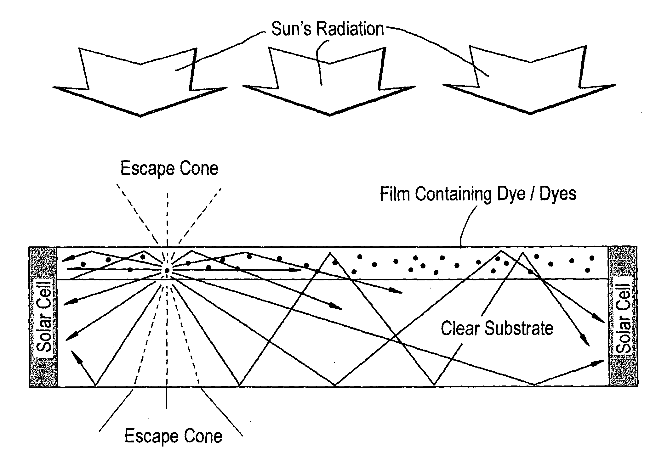
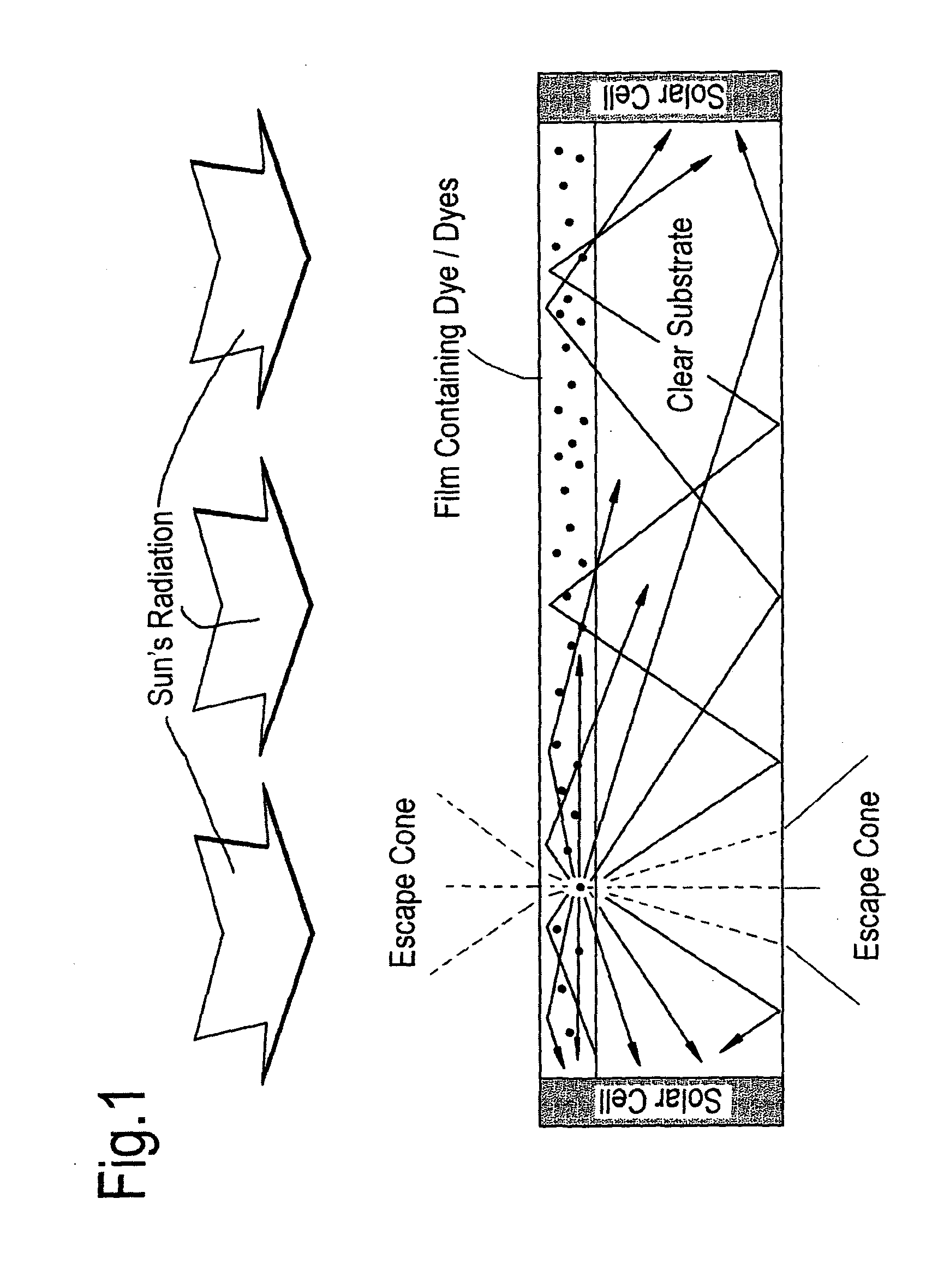
[0092]FIG. 1 schematically depicts the principle of operation of previous LSC devices, which typically comprise a single film 1 containing one or more luminescent compounds 2, 3 positioned on a clear substrate 4, which result in a lack of collection (depicted as an escape cone 5 in the figure) of some of the light emitted by the compounds subsequent to irradiation of the device by the sun. Such light is reflected out of the device; and therefore is not collected within the solar cells positioned proximally thereto, and represents a significant loss of energy in such systems.

example 2

An Embodiment of an LSC Device of this Invention

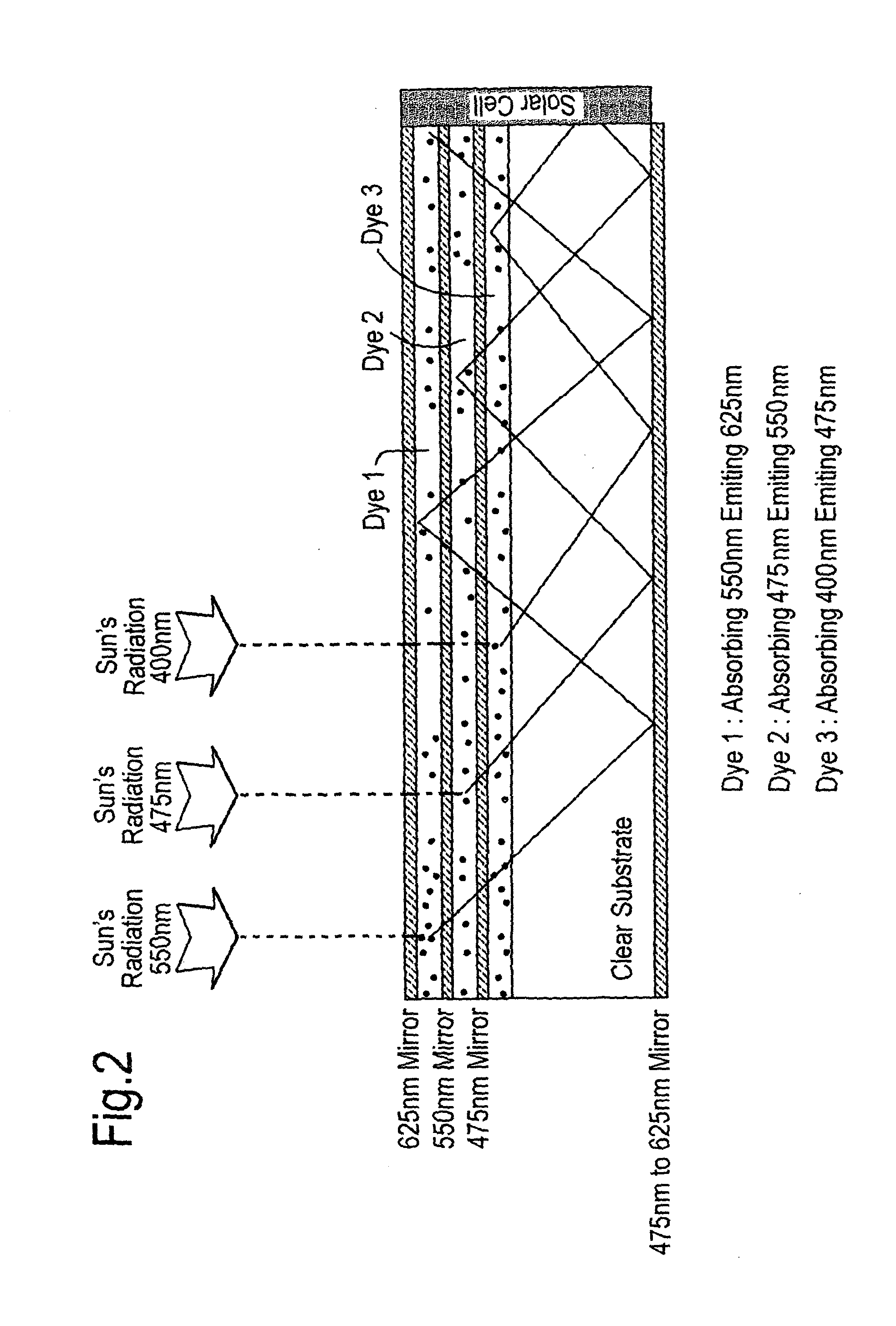
[0093]FIG. 2 schematically depicts an embodiment of a device of this invention. The devices of this invention, in marked contrast to previous devices, comprise two or more luminescent compounds, but each luminescent compound is located within a film which is apically bounded by a wavelength-selective mirror, which is reflective for light of a wavelength corresponding to that at which the proximally located compound emits light thereby specifically preventing or significantly diminishing the existence of an “escape cone”.

[0094]The device comprises a first film 6, apically bounded by a first mirror 7, and containing a first luminescent compound, 8, which compound emits light at a selective-wavelength which corresponds in value to that which is reflected by the apically located mirror 7. A second film 9 is positioned beneath the first film, and a second selective-wavelength mirror 10 is positioned there-between. The second film incorporat...


PUM


Abstract

The present invention is directed to luminescent solar concentrators, processes for the production of the same and uses thereof. The luminescent solar concentrators comprise a composite substrate including two or more films containing luminescent compounds and wavelength-selective mirrors, which concentrators may be connected to photovoltaic cells.

Description

FIELD OF THE INVENTION[0001]The present invention relates to methods for producing a luminescent solar concentrator (LSC). This invention further relates to an LSC having a wider absorption range and higher efficiency, minimizing inherent losses and reducing manufacturing costs of the LSC.BACKGROUND OF THE INVENTION[0002]The World's conventional energy supplies, based mainly on readily available fossil sources, are rapidly diminishing. The main short-term alternative to the energy crisis, the harnessing of nuclear fission energy, inspires much controversy, and practical realization of nuclear fusion technology has not yet occurred.[0003]Solar energy provides an obvious alternative energy source, which is clean and non-hazardous. Proper methods for the collection, concentration, storage, and conversion of solar light to be a practical solution is as yet lacking, since to date solar light is diffuse and intrinsically intermittent. Nonetheless, the feasibility of solar photovoltaic cel...

Claims


Application Information

Patent Timeline
Patent Type & Authority Applications(United States)
IPC IPC(8): H01L31/052H01L31/18H01L31/0232
CPCH01L31/055H01L31/0547Y02E10/52
Inventor SHMUELI, EITANLEIKOVICH, AMNONREISFELD, RENATA
Owner GREEN SUN ENERGY
Why Eureka
Try Eureka