

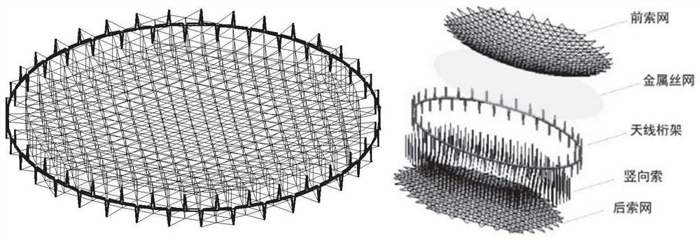
A New Mesh Ring Deployable Antenna Truss Structure
A truss structure and ring-shaped technology, applied in the direction of antennas, folded antennas, electrical components, etc., can solve the problems of reducing the height of the ring truss, the low storage of the expandable structure, and the limited opening diameter of the expandable antenna, so as to eliminate the risk of cold welding , Reduce the effect of contact friction
- Summary
- Abstract
- Description
- Claims
- Application Information
AI Technical Summary
Problems solved by technology
Method used
Image

Examples
Embodiment 1
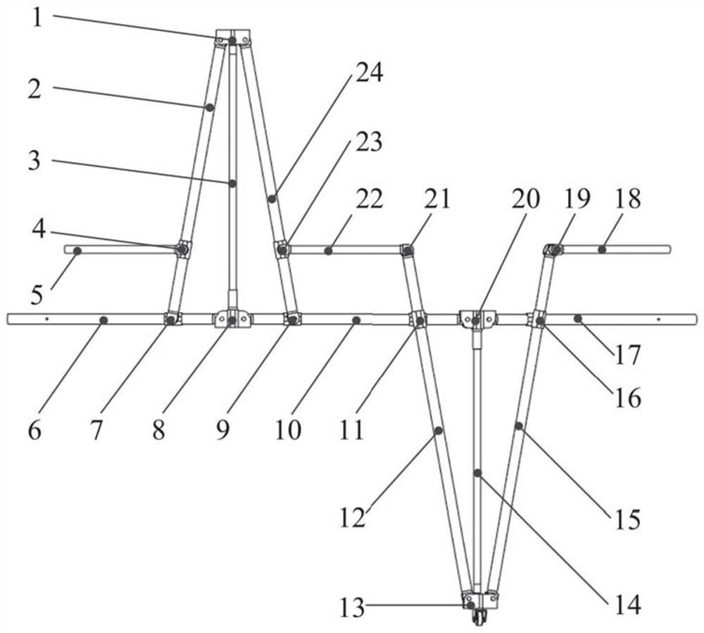
[0043] This embodiment provides a novel spatial annular deployable antenna truss structure, the structure of which includes multiple image 3 In the shown unit, adjacent units are connected to form a closed ring structure through the first lower synchronous rod link joint (19) and the second rigid frame rod joint (20); one of the structural units includes the first rigid frame Bar (6), the second rigid frame bar (10), the first upper synchronous bar (2), the second upper synchronous bar (24), the first lower synchronous bar (12), the second lower synchronous bar (15), The first connecting rod (5), the second connecting rod (22), the first telescopic rod group (3), the second telescopic rod group (14), the first rigid frame rod joint (8), the second rigid frame Rod joint (20), an upper synchronization rod joint (1), a lower synchronization rod joint (13), the first rigid frame rod upper synchronization rod hinged joint (7), the second rigid frame rod upper synchronization rod h...
Embodiment 2
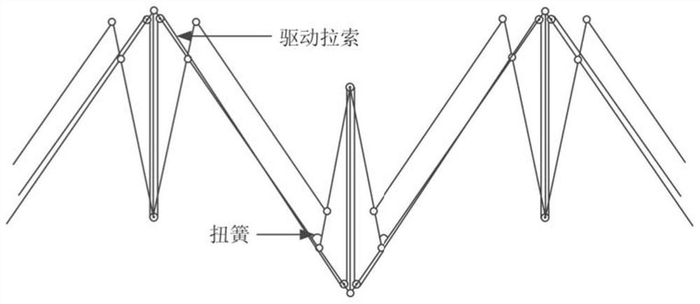
[0049] On the basis of Example 1, the mechanism adopts the joint driving method of torsion spring and cable to drive and unfold. Such as Figure 7 Shown, torsion spring is installed in first rigid frame bar_upper synchronous bar articulated joint (7), second rigid frame bar_upper synchronous bar articulated joint (9). Taking the hinged joint (7) of the first rigid frame bar_upper synchronizing bar as an example, one end of the torsion spring (7-3) is fixed inside the first upper synchronizing bar (2), and the other end is fixed on the fixed connecting shaft (7-5) Above, when the mechanism is in the retracted state, the torsion spring is curled and shrunk on the fixed connection shaft (7-5), storing elastic potential energy. In the early stage of mechanism deployment, the elastic potential energy stored in the torsion spring (7-3) is used to drive the mechanism to cross the dead point position. Afterwards, the motor winds up the cable and stretches the diagonal of the hinged f...
Embodiment 3
[0056] On the basis of Example 1, the entire ring-shaped deployable truss structure can be obtained. Figure 11 It is a schematic diagram of the meshed ring truss of the present invention in a fully folded state, Figure 12 It is a schematic diagram of the intermediate state of the meshed ring truss of the present invention, Figure 13 It is a schematic diagram of the mesh ring truss fully expanded state of the present invention.
[0057] use Figure 13 Ring truss, taking a ring-shaped expandable truss composed of 18 units as an example, the expanded diameter is 5000mm, the folded diameter is 924.21mm, the expanded height is 981.25mm, and the folded height is 774.98mm; considering joints, rods, and wire mesh As well as the quality of the flexible cable net, the overall mass of the antenna is about 21.422kg, and the calculated surface density is about 1.091kg / m 2 , compared with the same type of antenna, its diameter storage ratio has been improved, the height storage ratio ...
PUM
 Abstract
Description
Claims
Application Information