Device for bone fixation

Active Publication Date: 2009-12-15
AG CHUR SYNTHES +1
View PDF26 Cites 30 Cited by
  • Summary
  • Abstract
  • Description
  • Claims
  • Application Information

AI Technical Summary

Benefits of technology

[0012]In a preferred embodiment of the inventive device, the bone plate comprises a distally angled tab, the center of gravity of which, if projected into a cross-sectional area orthogonal to the longitudinal axis of the medullary pin, lies on a radius, which encloses an angle β of between 0°+100° and preferably of between +40° and +50°. These ranges for the angle β are for the embodiment of the inventive device at the right femur. For the embodiment of the inventive device, which can be used for the left femur, the angle β is between 0° and −100° and preferably between −40° and −50°. This arrangement permits the bone

Problems solved by technology

It is a disadvantage of this known device that the bone plate is disposed diametrically to the neck of the femur and protrude

Method used


Image

  • Device for bone fixation
  • Device for bone fixation
  • Device for bone fixation

Examples


Embodiment Construction

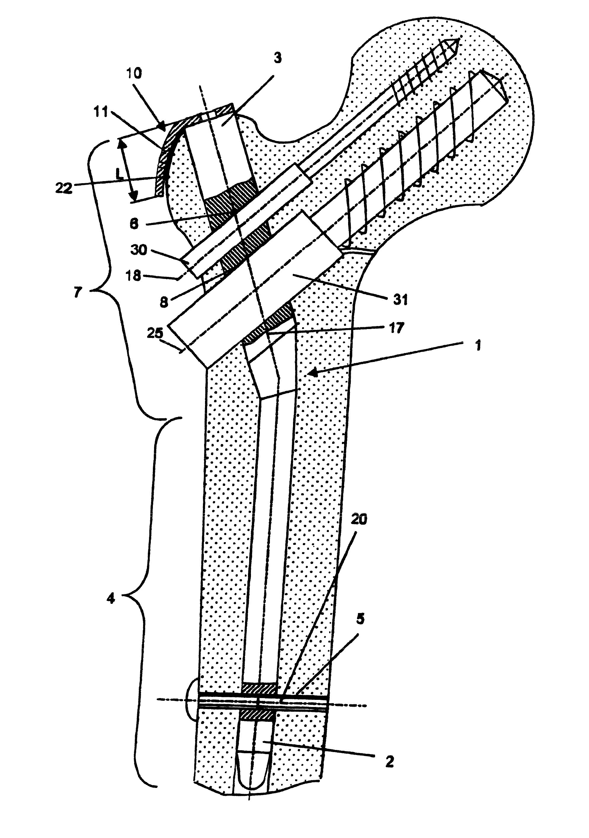
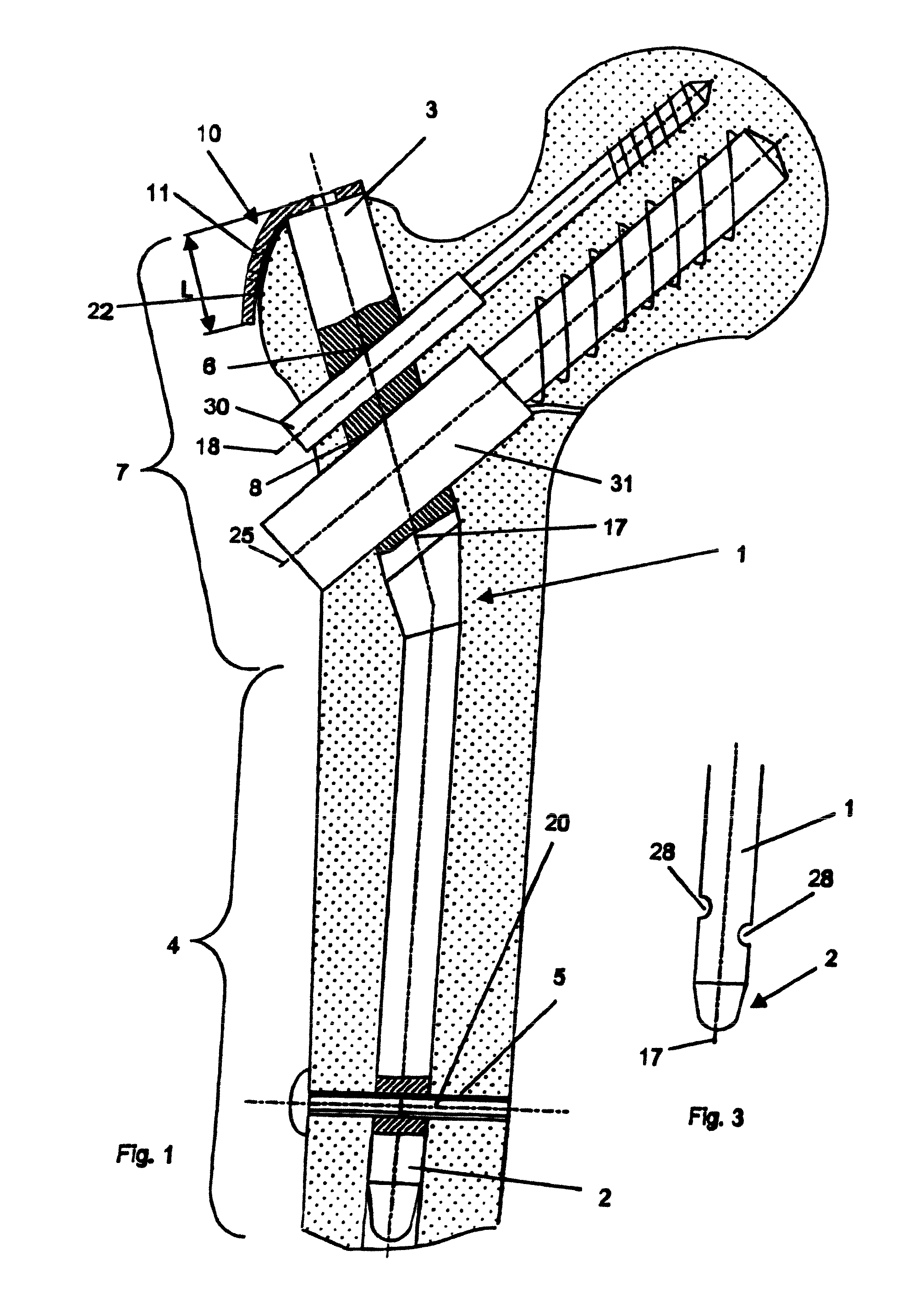
[0021]In FIG. 1, the medullary pin 1, introduced into the medullary space of a femur, is shown together with a bone plate 10, which is disposed at the greater trochanter. The medullary pin 1 has a longitudinal axis 17 and a proximal half 7 and a distal half 4 coaxial with this longitudinal axis 17. The bone plate 10 is angled distally and comprises a part, which is disposed transversely to the longitudinal axis 17 of the medullary pin 1, where the bone plate 10 is fastened by means of a screw connection 16 to the proximal rear end 3 of the medullary pin 1, and a tab 22, which extends towards the distal tip 2 of the medullary pin 1 and is provided with perforations 11. Furthermore, in its proximal half 7, the medullary pin 1 comprises a proximal transverse borehole 6 and a second transverse borehole 8, both of which are intended to accommodate hip screws 30 and 31. The transverse boreholes 6 and 8 pass through the medullary pin transversely to the longitudinal axis 17. The bone plate...


PUM


Abstract

A device for bone fixation includes an intramedullary pin and a bone plate. The intramedullary pin has a longitudinal axis with a distal tip configured for insertion into the medullary canal. The intramedullary pin also has at least one transverse borehole passing through it for accommodating a hip screw. The bone plate is disposed at the proximal rear end of the intramedullary pin and lies in contact with the greater trochanter.

Description

CROSS-REFERENCE TO RELATED APPLICATIONS[0001]This application is the United States National Stage application of PCT / CH02 / 00550, filed Oct. 3, 2002.FIELD OF THE INVENTION[0002]The invention relates to a bone fixation device, in particular for fixing fractures at the proximal femur.BACKGROUND OF THE INVENTION[0003]In the case of fractures at the proximal femur, especially in the case of pertrochantric fractures, medullary pins are frequently brought in to the femur for immobilizing bone fragments. Moreover, at the proximal end of the medullary pin, a bone plate is mounted, by means of which the forces and moments, acting on the head of the hip joint and the greater trochanter, can be transferred to the medullary pin.[0004]U.S. Pat. No. 5,356,410 to Pennig discloses a generic device, for which a perforated bone plate, coming to rest on the greater trochaner, is fastened by means of a screw connection to the proximal end of a medullary pin without transverse boreholes. It is a disadvan...

Claims


Application Information

Patent Timeline
IPC IPC(8): A61F2/30A61B17/78
CPCA61B17/744
Inventor MUNRO, CHAD RICHARDSENN, PETER
Owner AG CHUR SYNTHES
Why Eureka
Try Eureka