Patella resection clamp

a technology of resection clamp and saw guide, which is applied in the field of resection clamp, can solve the problems that the pat. no. 5,441,884 does not provide any method of setting the depth of the patella milling, and achieve the effect of facilitating the preparation of the natural patella

Inactive Publication Date: 2009-12-15
HOWMEDICA OSTEONICS CORP
View PDF24 Cites 54 Cited by
  • Summary
  • Abstract
  • Description
  • Claims
  • Application Information

AI Technical Summary

Benefits of technology

[0011]It is one aspect of the invention to provide an improved apparatus and method for facilitating the preparation of the natural patella to receive a patellar prosthesis.
[0012]It is an additional aspect of the invention to provide a clamping system which can hold the patella in position during resection without everting the patella.

Problems solved by technology

U.S. Pat. No. 5,441,884 does not provide any method of setting the depth of the patella milling based on the amount of bone remaining.

Method used


Image

  • Patella resection clamp
  • Patella resection clamp
  • Patella resection clamp

Examples


Embodiment Construction

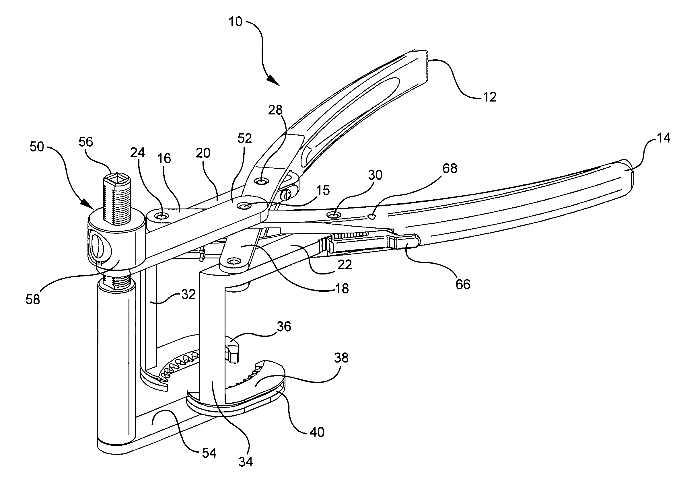
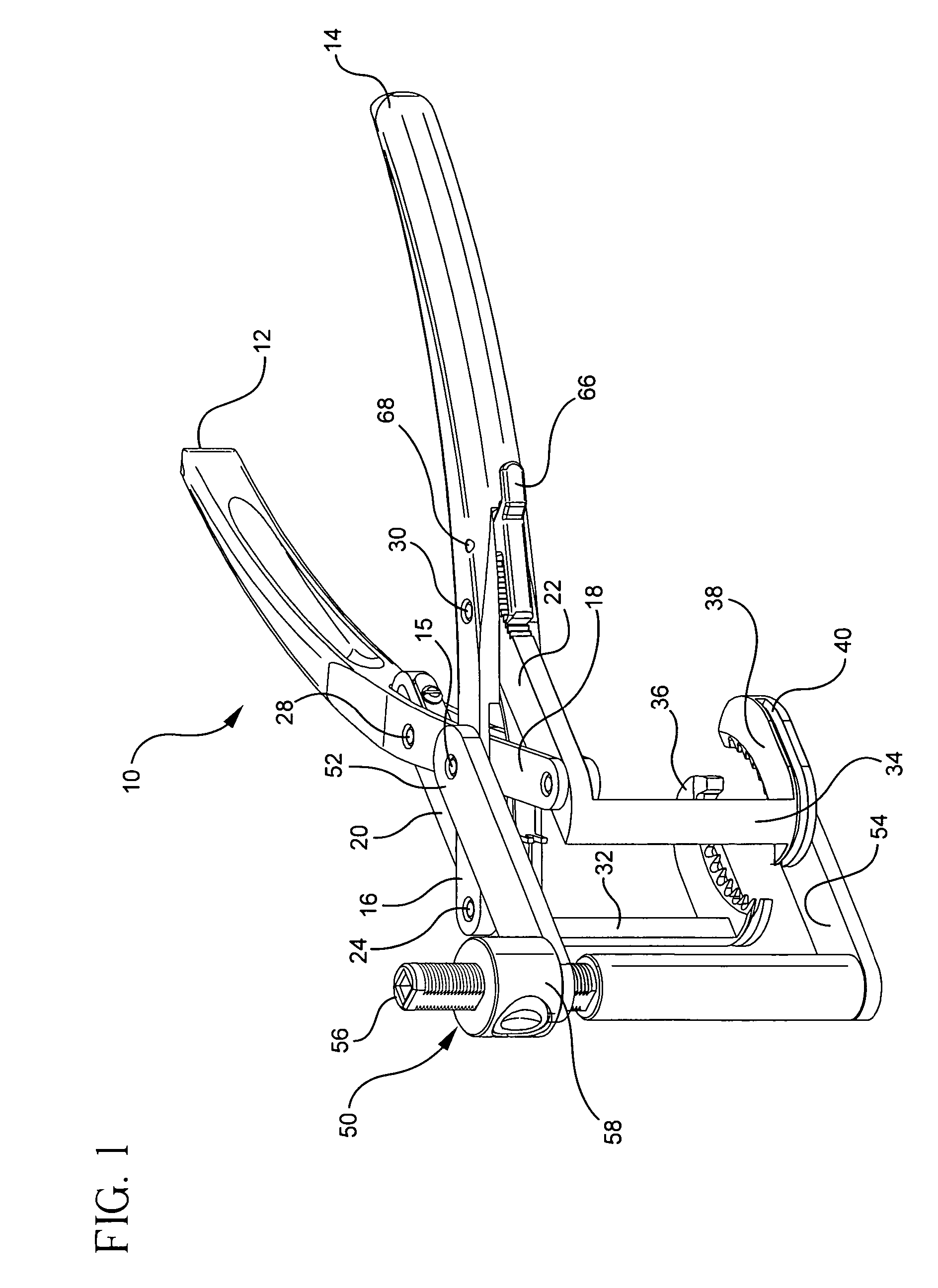
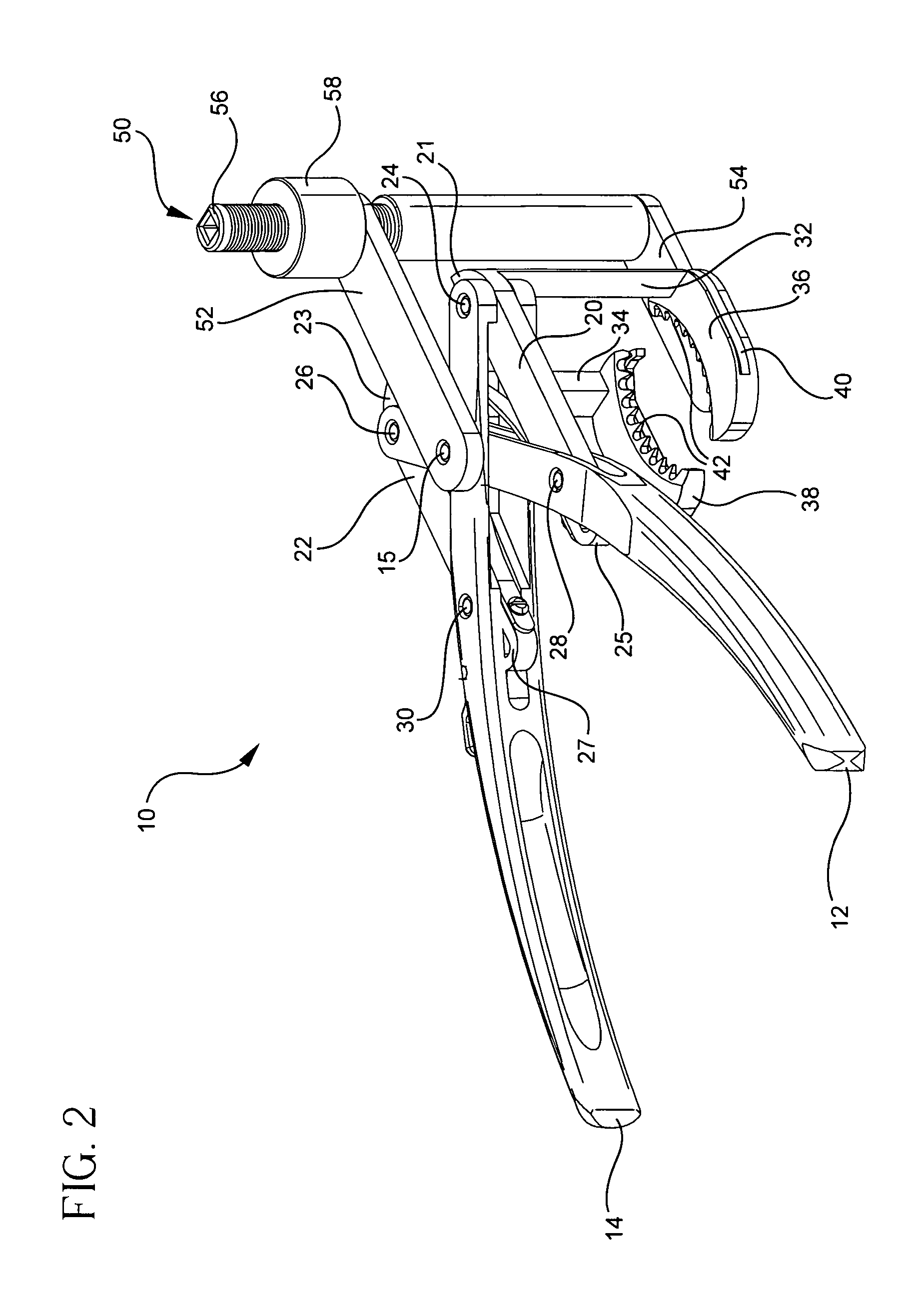
[0031]Referring to FIGS. 1 and 2, there is shown the patella resection clamp of the present invention generally denoted as 10. Clamp 10 has two handle portions 12 and 14 having first ends 16 and 18 each coupled to respective clamp arms 20 and 22. Arms 12 and 14 extend in parallel direction and are generally coplanar.

[0032]Each handle portion 12 and 14 is pivotally connected to first ends 21, 23 of both arms 20 and 22 by pivot pins 24 and 26, respectively. Each handle portion 12 and 14 is also connected to second ends 25 and 27 of arms 20 and 22 at pivot points 28 and 30. As can be seen, each handle portion 12, 14 is coupled to both arms 20, 22. Handle portion 12 is coupled to arm 22 at pivot point 26 and arm 20 at pivot point 28. Likewise, handle portion 14 is connected to arm 20 at pivot point 24 and arm 22 at pivot point 30. Handle portions 12 and 14 are interconnected by a pivot pin 15 which pivotally couples the handle portions in a scissor-like manner. Arms 20 and 22, respectiv...


PUM


Abstract

A patella resection clamp for use in resecting a patella has a first elongated handle portion and a second elongated handle portion. Each of the portions having first and second ends. The two handle portions are pivotally connected at a pivot point intermediate the first and second ends for rotation about a pivot axis. The second end of each of the elongated handle portions include a jaw with the jaw of the first and second handle portions spaced from the second end of the elongated portions in a direction parallel to the pivot axis. The jaws are spaced to form an opening therebetween for receiving the proximal and distal edges of the patella. The jaw portions including a saw blade guide surface or slot open to at least one of the first or second ends of each of said jaw portions. The guide surface or slot is for receiving a saw blade extending under (posteriorly) the handle portions and in a direction perpendicular to the pivot axis and perpendicular to the gripping direction of the jaws.

Description

BACKGROUND OF THE INVENTION[0001]A patellar clamp and saw guide are used during a total knee arthroplasty procedure to prepare the posterior surface of a patellar bone to accept a prosthetic implant.[0002]Typically, a surgeon will select a patellar prosthesis for implantation either by utilizing a resurfacing technique wherein the prosthetic patella will be resected and resurfaced or by an insetting procedure where the patella is inserted into the prepared surface of the patella. Accordingly, two varieties of guides could be available for connection to the patellar clamp and could be interchangeably connectable to the clamp. The interchangeable guides permit a surgeon to use the patellar clamp during either a total patellar bone resurfacing procedure or a patella insetting procedure.[0003]As used herein, when referring to bones or other parts of the body, the term “proximal” means closer to the heart and the term “distal” means more distant from the heart. The term “inferior” means ...

Claims


Application Information

Patent Timeline
Patent Type & Authority Patents(United States)
IPC IPC(8): A61B17/58A61B17/60A61F2/00
CPCA61B17/158
Inventor BASTIAN, ADAM
Owner HOWMEDICA OSTEONICS CORP
Why Eureka
Try Eureka