Phase shifter circuit with proper broadband performance

a technology of phase shifter and broadband performance, which is applied in the direction of impedence networks, multiple-port networks, electrical apparatus, etc., can solve the problems of increasing circuit size, circuit size, increasing the time required for signal propagation inside the filter, etc., and achieves a small phase deviation, superior broadband performance

Inactive Publication Date: 2009-12-15
FUJITSU LTD
View PDF7 Cites 9 Cited by
  • Summary
  • Abstract
  • Description
  • Claims
  • Application Information

AI Technical Summary

Benefits of technology

[0017]According to at least one embodiment of the present invention, a phase shifter circuit is provided that is superior in terms of broadband performance, i.e., has a smaller phase deviation over the intended frequency band, compared with related-art circuits.

Problems solved by technology

This results in increased circuit size.
An increase in circuit size means an increase in the time required for signal propagation inside the filter, which gives rise to a problem in that a phase deviation (i.e., absolute phase deviation responsive to frequency) within the band increases.
There are also an increase in loss and cost increase.
In the case of the hybrid coupler shown in FIG. 2, the loss is relatively small, but this coupler is not suitable for broadband operations because of the use of ¼ wavelength transmission lines.
In this manner, related-art 90-degree phase shifters have a problem of poor broadband performance, i.e., a problem of a large phase deviation within the band.

Method used


Image

  • Phase shifter circuit with proper broadband performance
  • Phase shifter circuit with proper broadband performance
  • Phase shifter circuit with proper broadband performance

Examples


Embodiment Construction

[0037]In the following, embodiments of the present invention will be described with reference to the accompanying drawings.

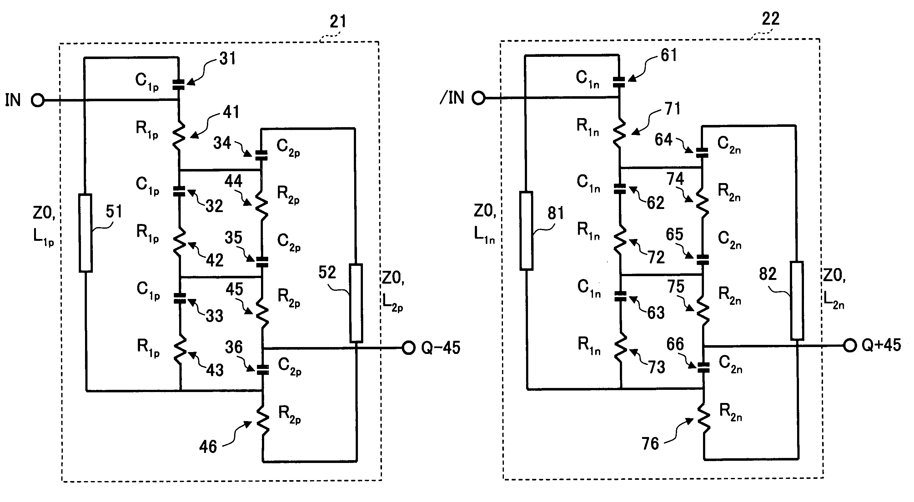
[0038]FIGS. 3A and 3B are drawings showing an example of the circuit configuration of a 90-degree phase shifter according to the present invention. The 90-degree phase shifter of the present invention includes a −45 degree phase shifter 21 configured to receive a positive-phase signal IN of differential input signals as an input thereof to delay its phase by 45 degrees and a +45 degree phase shifter 22 configured to receive a negative-phase signal / IN as an input thereof to advance its phase by 45 degrees. An output signal Q−45 having a 45-degree phase delay generated by the −45 degree phase shifter 21 and an output signal Q+45 having a 45-degree phase advance generated by the +45 degree phase shifter 22 are different in phase by 90 degrees. In this manner, signals having a 90-degree phase difference are generated.

[0039]The −45 degree phase shifter 21 shown in F...


PUM


Abstract

A phase shifter circuit includes a plurality of first series circuits each comprised of a series connection of one capacitor and one resistor, a first circuit element including at least inductance connecting between a first end and a second end of a chain structure made by connecting the plurality of first series circuits in series, the first circuit element and the chain structure together constituting a first loop circuit, a plurality of second series circuits each comprised of a series connection of one capacitor and one resistor, a second circuit element including at least inductance connecting between a first end and a second end of a chain structure made by connecting the plurality of second series circuits in series, the second circuit element and the chain structure together constituting a second loop circuit, and a plurality of connection lines connecting between the first loop circuit and the second loop circuit.

Description

CROSS-REFERENCE TO RELATED APPLICATIONS[0001]The present application is based upon and claims the benefit of priority from the prior Japanese Patent Application No. 2006-191874 filed on Jul. 12, 2006, with the Japanese Patent Office, the entire contents of which are incorporated herein by reference.BACKGROUND OF THE INVENTION[0002]1. Field of the Invention[0003]The present invention generally relates to circuits for converting the characteristics of a signal, and particularly relates to a phase shifter for changing the phase of a signal.[0004]2. Description of the Related Art[0005]Phase shifters for changing the phase of a signal are widely used as a component for a system such as a wired / wireless communication apparatus or measurement apparatus utilizing microwave bands or milliwave bands. In the orthogonal modulation which is widely used in the wireless communication system of today, for example, a 90-degree phase shifter is used as an indispensable component in order to generate ...

Claims


Application Information

Patent Timeline
Patent Type & Authority Patents(United States)
IPC IPC(8): H03H7/18H03H7/20
CPCH03H7/185H03H7/21H03H7/19H03H2007/0192
Inventor NAKASHA, YASUHIROHIROSE, TATSUYA
Owner FUJITSU LTD
Why Eureka
Try Eureka