
System and method for controlling network traffic

a network traffic and system technology, applied in the field of system for controlling a network traffic path, can solve the problems of many inefficient and unreasonable situations, forced to use an inefficient flooding path, and use an optimized switching path

Inactive Publication Date: 2009-12-15
CHO CHANG HWAN +1
View PDF5 Cites 15 Cited by
  • Summary
  • Abstract
  • Description
  • Claims
  • Application Information

AI Technical Summary

Benefits of technology

"The present invention is a network traffic controlling system and method that allows multiple switches connected to each other to share information about their neighbors and the like. This allows each switch to provide better service to its neighbors and improve network traffic control. The system includes multiple switches, ports, and a switching control module that real-time exchanges switch state information with other switches and selects ports based on the switch state information to forward data frames. The method includes steps of building a neighborship, synchronizing switch state information, updating and creating a switching table, and processing data frames. The technical effects of the invention are improved network traffic control and better service to neighbors."

Problems solved by technology

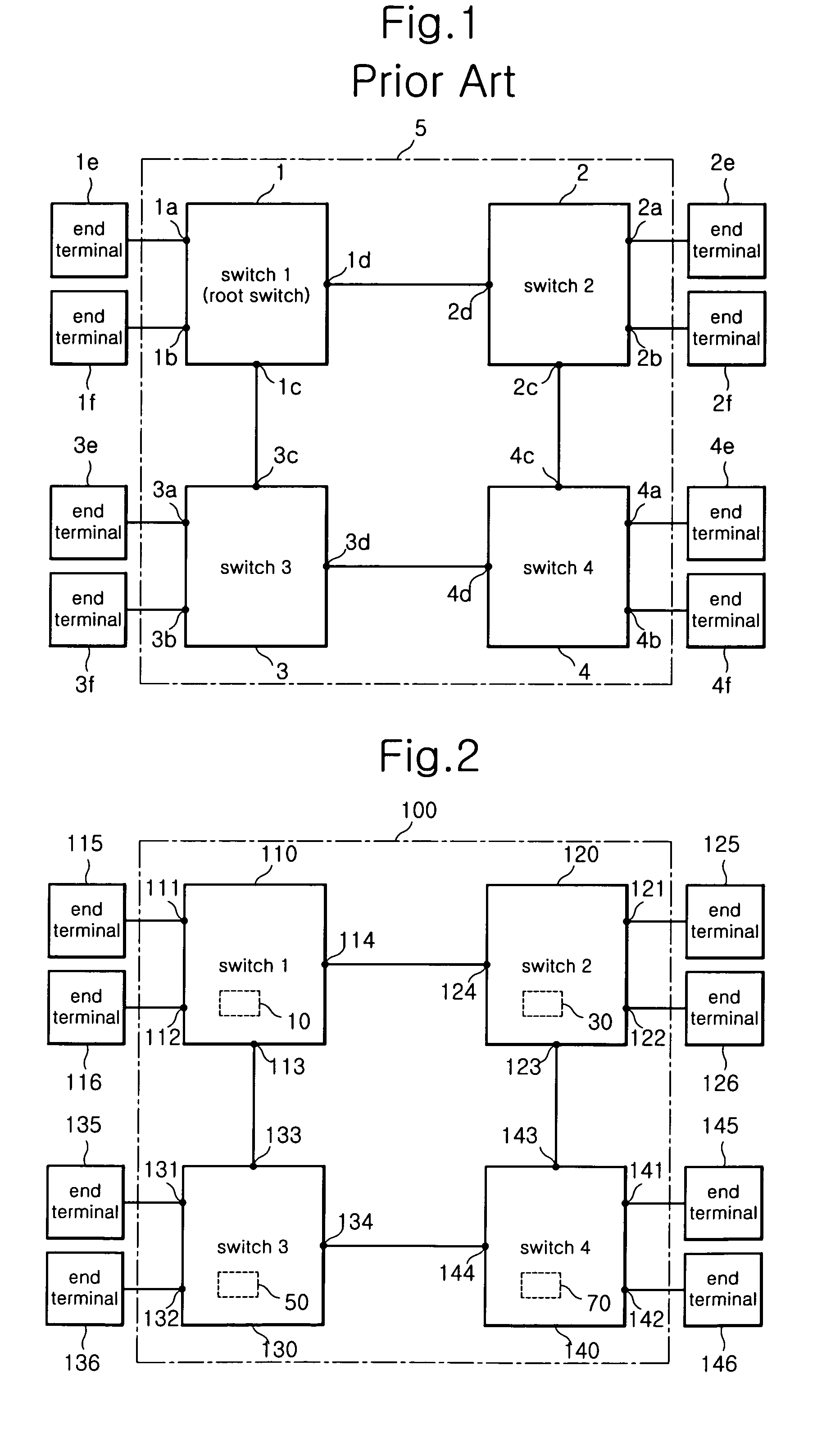
However, when the frame switching operations of the switches 2, 3, 4 are determined by the switch 1, i.e., root switch, there occur many inefficient and unreasonable situations.
In other words, according to the single root switch based topology of the prior art, it is highly probable that each of the switches 2, 3, 4 cannot use an optimized switching path when switching frames and is forced to use an inefficient flooding path when flooding frames.
In addition, under situation that a switching path is determined in reference to the false root switch, i.e., the switch 4, if an ill-intentioned user connects an monitoring tool to the switch 4 and maliciously monitors all frames passing through the switch 4, users using each of the end terminals 1e, 1f, 2e, 2f, 3e, 3f suffer such serious damage that the user's information is leaked to the ill-intentioned user or modified or damaged.
In other words, according to the single root switch based structure of the prior art, the user (each of the switches) cannot efficiently cope with security infringement of a network using a non-authenticated false root switch or similar tool or program.
Accordingly, switching path load balancing in the same VLAN cannot be achieved.

Method used


Image

  • System and method for controlling network traffic
  • System and method for controlling network traffic
  • System and method for controlling network traffic

Examples


Embodiment Construction

[0044]Hereinafter, a preferred embodiment of the present invention will be described with reference to the accompanying drawings. In the following description of the present invention, a detailed description of known functions and configurations incorporated herein will be omitted when it may make the subject matter of the present invention rather unclear.

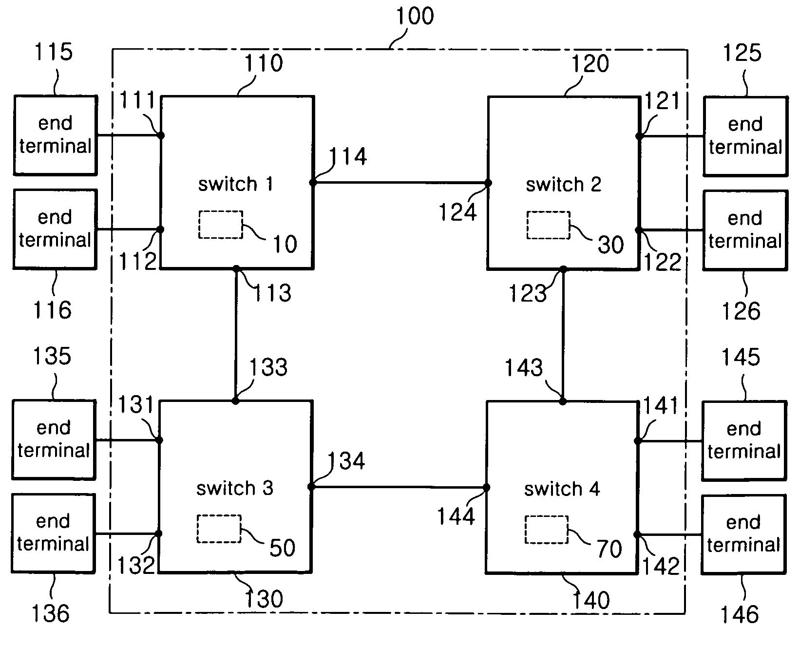
[0045]As shown in FIG. 2, a network traffic controlling system 100 according to an embodiment of the invention is a systematically structured system comprising multiple switches 110, 120, 130, 140 connected to each other and multiple end terminals 115, 116, 125, 126, 135, 136, 145, 146 arrangedto eachofthe switches 110, 120, 130, 140.

[0046]At this time, ports 111, 112, 121, 122, 131, 132, 141, 142 each connects end terminals 115, 116, 125, 126, 135, 136, 145, 146 to switches 110, 120, 130, 140, and ports 113, 114, 123, 124, 133, 134, 143, 144 each connects other switches.

[0047]Hereinafter, for convenience sake, it is assumed that I...


PUM


Abstract

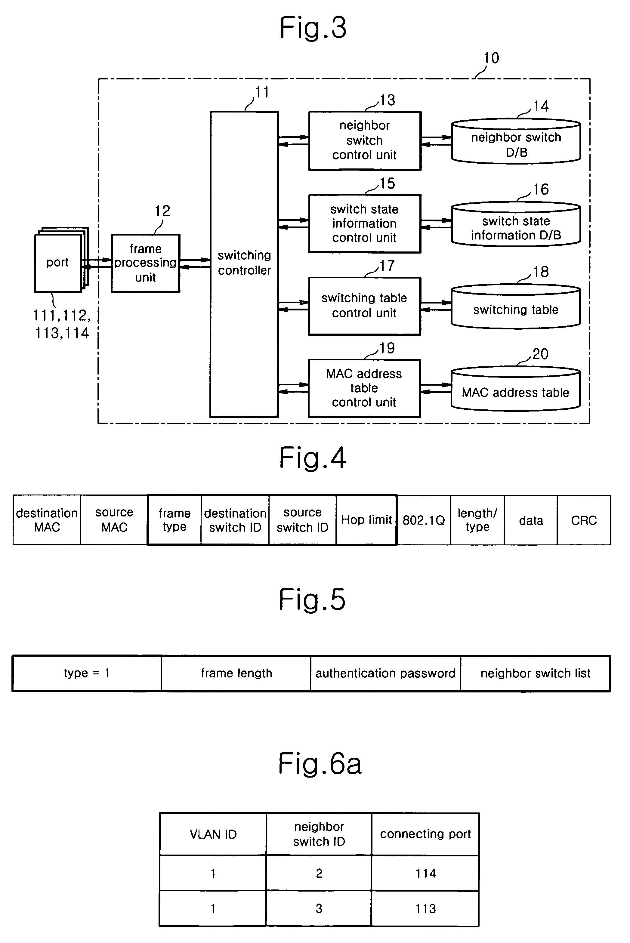
Disclosed are system and method for controlling a network traffic. According to the invention, all switches connected with the same VLAN are allowed to share an inherent ID of each switch, a port ID connecting the switches and information about a bandwidth so as to calculate an optimized path that each switch is connected to other switches. For doing so, each switch is systematically structured to comprise a computation module capable of structuring a neighbor relation with other switches, a computation module capable of exchanging / sharing the switch state D / B with the other switches, and synchronizing a corresponding switch state D / B, a computation module capable of creating / updating a switching table, and a computation module capable of switching and flooding a received data frame through an optimized path with reference to the created / updated switching table.

Description

CROSS-REFERENCE TO RELATED APPLICATIONS[0001]This application claims all benefits of Korean Patent Application No. 2005-0054514 filed on Jun. 23, 2005 in the Korean Intellectual Property Office, the disclosures of which are incorporated herein by reference.BACKGROUND OF THE INVENTION[0002]1. Field of the Invention[0003]The present invention relates to a system for controlling a network traffic path, and more particularly to a network traffic controlling system allowing all switches consisting a network to individually determine the best switching path, rather than to determine switching path by a single root switch as the prior art. In addition, the invention relates to a network traffic controlling method using such network traffic controlling system.[0004]2. Description of the Prior Art[0005]As shown in FIG. 1, according to the prior art, a switch network 5 comprises multiple switches 1, 2, 3, 4 connected together and multiple end terminals 1e, 1f, 2e, 2f, 3e, 3f, 4e, 4f connected...

Claims


Application Information

Patent Timeline
Patent Type & Authority Patents(United States)
IPC IPC(8): H04L12/24
CPCH04L12/4641H04L45/02H04L49/354H04L45/03H04L12/28
Inventor CHO, CHANG HWANJEON, TAE BOONG
Owner CHO CHANG HWAN
Learn More