
Network system, control system, information appliance, and program

a network system and information appliance technology, applied in the field of network system, control system, information appliance, and program, can solve the problems of not being able to recognize which of a plurality of information appliances, not being able to specify and deal with a physical position of information appliances, and not being able to take into account recognizing

Active Publication Date: 2009-12-15
MAXELL HLDG LTD
View PDF3 Cites 0 Cited by
  • Summary
  • Abstract
  • Description
  • Claims
  • Application Information

AI Technical Summary

Benefits of technology

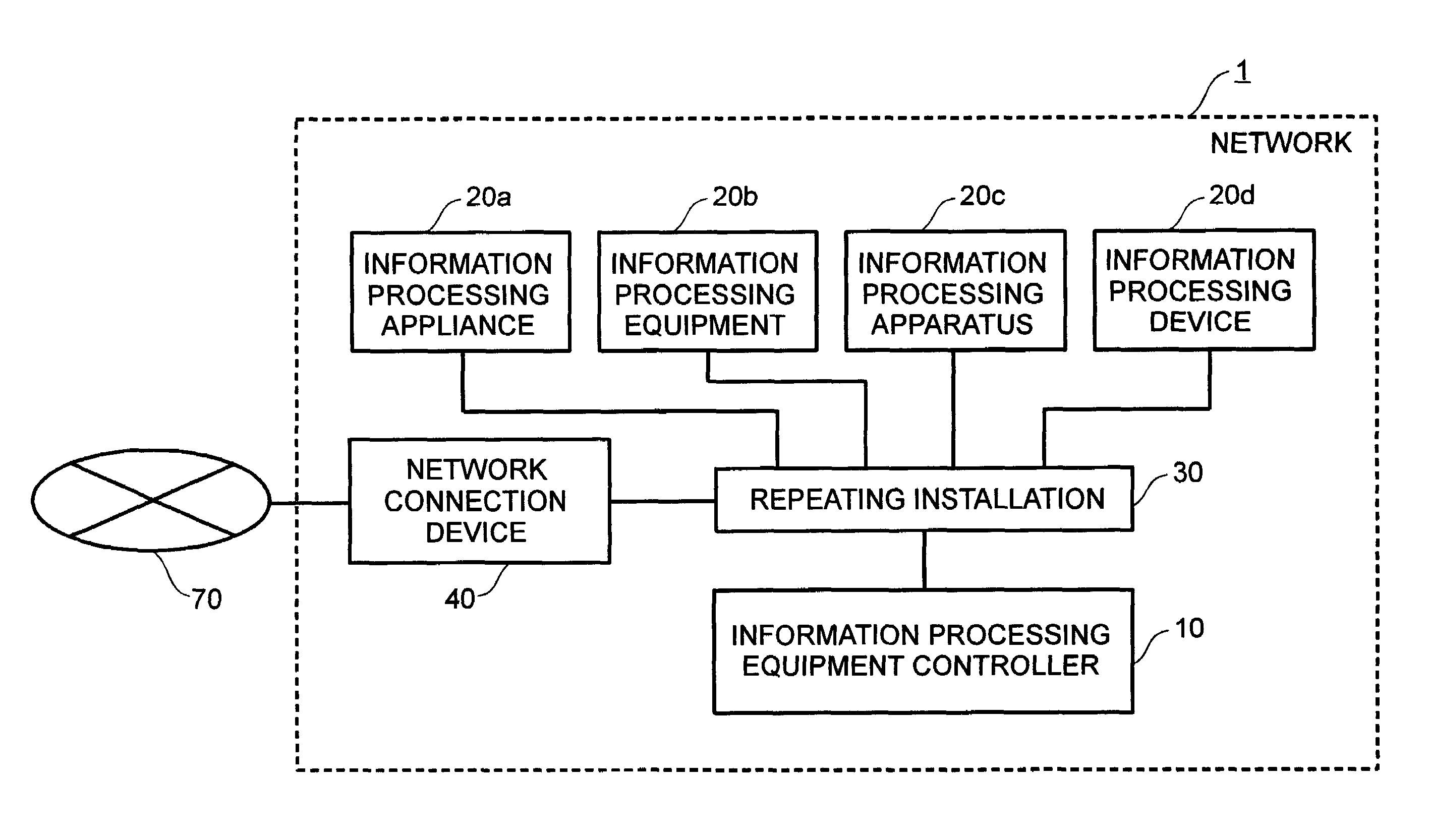
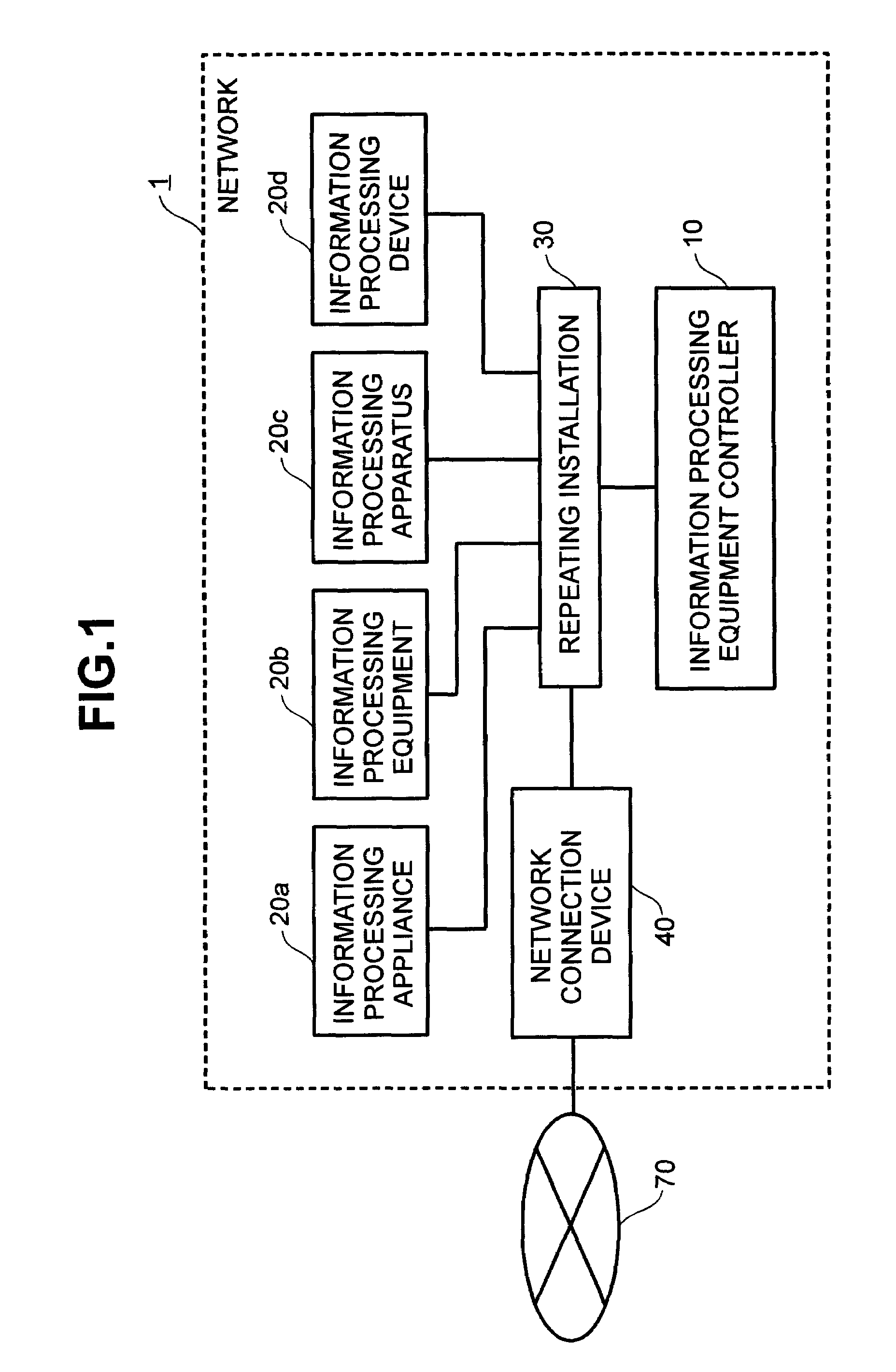
The invention provides a network system with multiple information appliances and a control system. The control system receives user selection of an information appliance and sends a response command to the selected appliance. The information appliance has response means to implement the response processing. The control system also stores information unique to each information appliance and creates image data to display the appliance on the screen. This makes it easy for users to recognize where the appliance is physically located. The invention also provides a control system that can light up or off certain appliances based on user selection or malfunctioning. Overall, the invention improves the user experience and facilitates the recognition of physical positions of information appliances in a network system.

Problems solved by technology

Even when respective information appliance can be theoretically specified with the use of IP addresses or the like, however, it is not possible to recognize which of a plurality of information appliance corresponds to a specified information appliance and where the specified information appliance is physically present.
For example, even when it has proved that an information appliance specified by a certain IP address performs an abnormal processing, it is not easy to specify and deal with a physical position of the information appliance.
However, the technique described in Patent document 1 still takes no account of recognizing which of a plurality of information appliance corresponds to a specified information appliance and where the specified information appliance is physically present in a certain network.
This problem becomes conspicuous particularly in those LAN's in is offices, to which many information appliance are connected, or home networks, to which all electric appliances are expected to be connected as information household electrical appliances.

Method used


Image

  • Network system, control system, information appliance, and program
  • Network system, control system, information appliance, and program
  • Network system, control system, information appliance, and program

Examples


first embodiment

[0060]An explanation will be given to the invention with reference to a flowchart shown in FIG. 5.

[0061]In the embodiment, the information appliance controller 10 first receives selection of a particular information appliance 20 in the network 1 from a user (S101). While a way to receive selection of a information appliance 20 is optional, the input unit 18 such as mouse, or the like, on a screen 500 showing, for example, a configuration of the network 1 shown in FIG. 4 can be used to receive designation of a block corresponding to a particular information appliance 20. Also, a keyboard may be used to receive nomenclatures of the information appliance 20.

[0062]When receiving an indicator lighting-on command in a state, in which a particular information appliance 20 is selected (S102), the indicator control unit 102 of the information appliance controller 10 sends a packet for lighting-on of an indicator, to the selected information appliance 20 (S103).

[0063]The indicator lighting-on...


PUM


Abstract

A network system which includes a plurality of information appliances and a control system. The control system includes a response control device for receiving selection of an information appliance and response instructions from a user and sending a response command to the selected information appliance. The information appliance includes a response device for implementing a response processing, and an information appliance control device for receiving a response command to have the response device implementing a response processing.

Description

BACKGROUND OF THE INVENTION[0001]The present invention relates to a network composed of a plurality of information appliance, and more particular, to a network enabling a user to readily recognize physical positions of the respective information appliance.[0002]Computer networks become widespread and LAN's (Local Area Network), to which a plurality of information appliance, such as computers, printers, or the like are connected, are built in may offices. Also, domestic networks, that is, so-called home information appliance have been gradually generalized.[0003]Further, it is expected that not only computers, printers, or the like but also all electric appliances have a communication function to be connected as so-called information household electrical appliances to networks in the future.[0004]In such network, intercommunication is made with the use of, for example, Internet Protocol (IP). In an IP network, IP addresses allotted to respective information appliance can be used to i...

Claims


Application Information

Patent Timeline
Patent Type & Authority Patents(United States)
IPC IPC(8): H04W4/00G06F13/00H04L12/28
CPCH04L12/2809H04L12/282H04L2012/285
Inventor IWABUCHI, KAZUNORI
Owner MAXELL HLDG LTD
Learn More