Transport system with inductive energy transfer

a technology of inductive energy transfer and transport system, which is applied in the direction of steering control, non-vehicle mounted steering control, rail device, etc., can solve the problems of reducing the service life of the transport system. , to achieve the effect of simplifying the construction of the transport system and the control of the vehicl

Active Publication Date: 2009-12-22
ROFA ROSENHEIMER FORDERANLAGEN GMBH
View PDF6 Cites 6 Cited by
  • Summary
  • Abstract
  • Description
  • Claims
  • Application Information

AI Technical Summary

Benefits of technology

[0011](b-4) a control unit which controls said two drive wheels in response to signals of said sensor unit for minimizing a deviation of said vehicle from said floor track signal,
[0038]According to a preferred embodiment of the present invention the drive wheels and the idle roller(s) and optionally the swivelling roller(s) comprise hard rubber for increasing the abrasion resistance thereof.

Problems solved by technology

Such mechanical guidance has the disadvantage that the track body in which the guide channel is provided is abraded during use.
Such abrasion is particularly problematic, in a case wherein heavy loads are transported by the electric transport vehicles, especially in curves of the track system.
The replacement of a track body or of major parts of the track body leads to unwanted long down-time of the transport system, and thus to a machine down-time in the whole assembly line in which the transport system is used.
Since such transport systems are used in industry, e.g. in the automobile industry, a long down-time of an assembly-line has a large impact on the production costs and thus the efficiency of the manufacture.
Thus, a difficult and complicated control of signals of at least three sensor units is necessary.
Such a system is unreliable and expensive.

Method used


Image

  • Transport system with inductive energy transfer
  • Transport system with inductive energy transfer
  • Transport system with inductive energy transfer

Examples


Embodiment Construction

[0045]The present invention is now described in further detail with reference to the accompanying drawings. Corresponding or equivalent elements of the transport system of the present invention illustrated in different drawings are designated with the same reference signs.

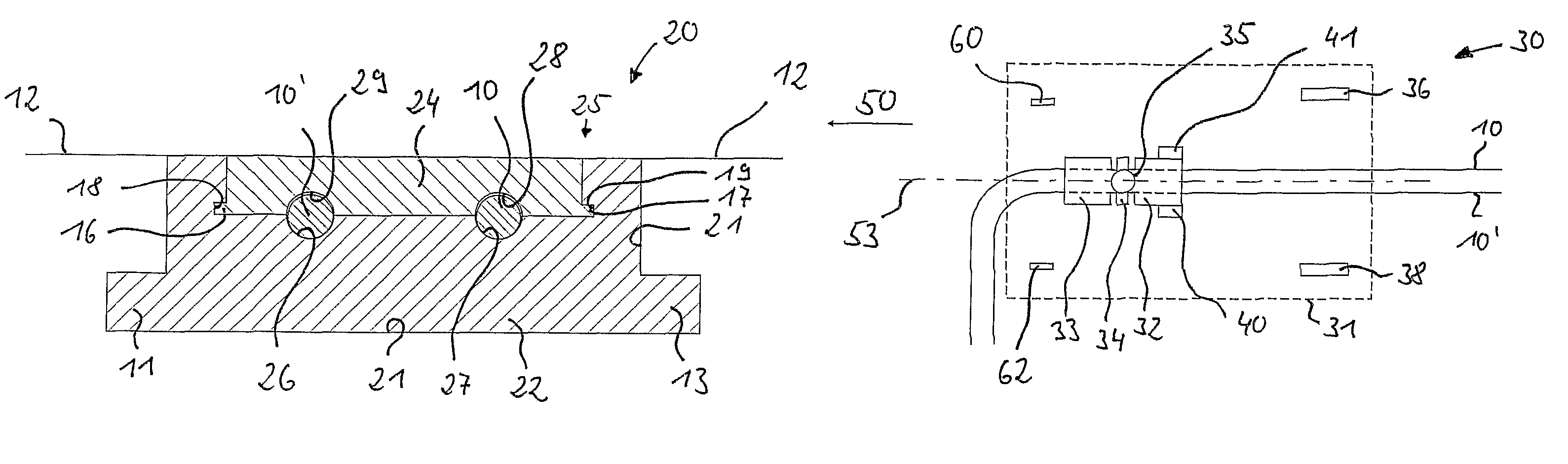
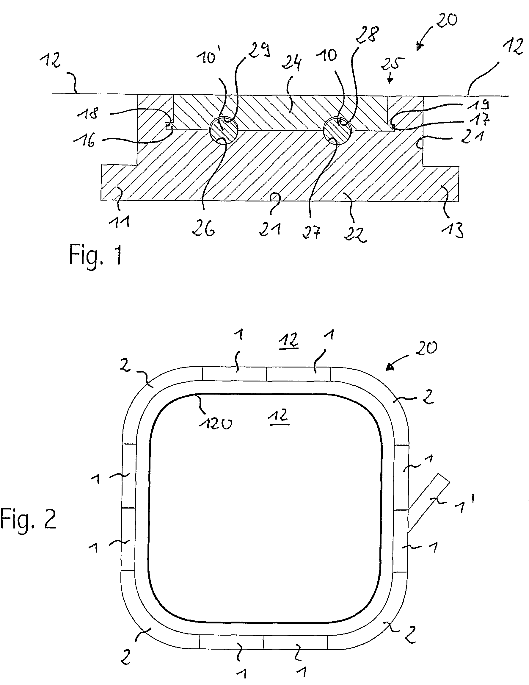
[0046]FIG. 1 shows a sectional view of an insulating track body 20 of a transport system according to a particularly preferred embodiment of the present invention. The insulating track body comprises a lower part 22 and an upper part 24. The lower part is usually buried in a groove or channel 21 in the floor. The lower part 24 comprises in its top surface parallel grooves 26 and 27. The upper part comprises in its bottom surface parallel grooves 28 and 29 which are complementary in shape to the parallel grooves 26 and 27. “Parallel” means that the grooves 26 and 27, and 28 and 29, respectively, are provided in a constant distance. This means that the grooves are linear parallel on a portion of the track body which ...


PUM


Abstract

A transport system is provided, comprising an underfloor high frequency alternate current primary conductor for providing an electromagnetic field extending along the primary conductor for inductive energy transfer. The transport system includes at least one electric transport vehicle comprising two individually controllable and individually drivable drive wheels. At least one pick-up unit with a secondary conductor for the inductive energy transfer is pivotable relative to the vehicle and comprises at least one idle roller adapted for being continuously contacted with the travel surface. The electric transport vehicle includes a sensor unit adapted for sensing continuously a floor track signal. A control unit is provided to control the two drive wheels in response to signals of the sensor unit for minimizing a deviation of the vehicle from the floor track signal.

Description

TECHNICAL FIELD AND BACKGROUND OF THE INVENTION[0001]The present invention relates to a transport system with inductive energy transfer from an underfloor primary conductor to a secondary conductor in an electric transport vehicle, an electric transport vehicle of such a system, and a method of guiding such a vehicle of such a transport system.[0002]A transport system with inductive energy transfer from an underfloor primary conductor to a secondary conductor in an electric transport vehicle is known from the following patent specification and patent applications: DE 199 47 368 C1, DE 199 55 042 A1, and DE 100 13 767 A1.[0003]The transport systems described in DE 199 47 368 C1 and DE 199 55 042 A1 comprise electric transport vehicles which are guided mechanically. These electric transport vehicles have at least three guide bolts protruding into a guide channel provided in an underfloor track system for engagement and for guidance of the transport vehicles along the track system. Suc...

Claims


Application Information

Patent Timeline
Patent Type & Authority Patents(United States)
IPC IPC(8): B62D1/00B60L5/00B60M7/00
CPCB60M7/00B60L5/005B60L5/00B60L5/39
Inventor KOZSAR, WOLFGANG
Owner ROFA ROSENHEIMER FORDERANLAGEN GMBH
Why Eureka
Try Eureka