
Connector / bushing assembly for electrical junction boxes

a technology for connecting parts and junction boxes, which is applied in the direction of cable terminations, insulating bodies, manufacturing tools, etc., can solve the problems of poor protection of cables at junction boxes, poor difficult installation of cables, so as to improve the grip of nut teeth, facilitate cable insertion, and improve the effect of elasticity

Active Publication Date: 2009-12-22
ATKORE STEEL COMPONENTS INC
View PDF20 Cites 28 Cited by
  • Summary
  • Abstract
  • Description
  • Claims
  • Application Information

AI Technical Summary

Benefits of technology

[0008]The nut 102, which may also be formed of metal, plastic, and / or other materials, includes a nut junction end 104 (shown best in FIGS. 2 and 3) and an opposing nut entry end 106 (shown best in FIG. 1). An outer nut surface 108, as well as an inner nut surface 110, extends between the nut junction end 104 and nut entry end 106. The inner nut surface 110, which bears nut threading 112, bounds an inner nut passage 114 which extends along the axis of the nut 102 between the nut junction end 104 and nut entry end 106. One or more box wall engagement flanges 116 are situated at or adjacent the nut junction end 104, with the box wall engagement flange(s) 116 extending radially outwardly from the outer nut surface 108 at the nut junction end 104 along a plane oriented at least substantially perpendicular to the axis of the inner nut passage 114. In the exemplary version of the connector assembly 100 depicted in the drawings, the engagement flange 116 is provided as a series of spaced nut teeth 118 which are arrayed circumferentially about the outer nut surface 108 at the nut junction end 104. These spaced nut teeth 118 allow the nut 102 to function in the manner of a lock nut, with the teeth frictionally engaging an adjacent junction box wall 202. To enhance the grip of the nut teeth 118 (or other engagement flange 116), at least a portion of each nut tooth 118 may be inclined in relation to a plane extending perpendicular to the axis of the inner nut passage 114, with the inclined portion extending laterally away from the inner and outer nut surfaces 108 in the axial direction as the nut tooth 118 extends radially away from the nut junction end 104. Thus, the inclined portion of the nut tooth 118 extends away from the nut 102 to better “bite into” the junction box wall 202.
[0010]The male connector 130 (see FIG. 5) includes an outer connector surface 132 and an opposing inner connector surface 134. The inner connector surface 134 surrounds an inner connector passage 136 which extends axially between a connector junction end 138 and an opposing connector entry end 140. The connector junction end 138 preferably bears connector threading 142, and is sized to be received in a box wall passage 206 of the junction box 200. The connector junction end 138 is also configured to fit within the inner nut passage 114 at the nut junction end 104, with the connector junction end 138 being situated between the liner 150 (more specifically, the liner floating end 154) and the nut 102 (more specifically, the nut junction end 104), and with the liner floating end 154 being situated within the inner connector passage 136. In this arrangement, the connector threading 142 complementarily engages the nut threading 112 within the inner nut passage 114. Thus, the nut 102 engages the male connector 130 on the opposite side of the box wall 202 of the junction box 200, with the nut 102 fit over the connector junction end 138, and with the box wall engagement flanges 116 (e.g., nut teeth 118) of the nut 102 engaging the box wall 202. At the same time, the liner 150 extends within the inner nut passage 114 from the nut entry end 106, and into the inner connector passage 136. The liner 150 therefore insulates any cable extending therein from the nut 102 (assuming the liner is nonconductive), deters moisture from entering the inner nut and connector passages 114 and 136 via the seam between the nut 102 and the male connector 130, and also helps to eliminate sharp edges bounding or within the nut and connector passages 114 and 136 which might interfere with insertion and / or removal of cable.

Problems solved by technology

However, prior bushings manufactured for the aforementioned purposes tend to suffer from a number of disadvantages.
Many provide poor protection for the cable at the junction box (e.g., providing a connection at the junction box which is susceptible to moisture, and / or which presents sharp corners / edges within the bushing).
Also, many are made of multiple parts which are time-consuming to assemble, and / or which can be difficult to install, particularly when it is considered that bushings must often be installed “blind” (i.e., by touch, without being able to easily see the bushing as it is being installed).

Method used


Image

  • Connector / bushing assembly for electrical junction boxes
  • Connector / bushing assembly for electrical junction boxes
  • Connector / bushing assembly for electrical junction boxes

Examples


Embodiment Construction

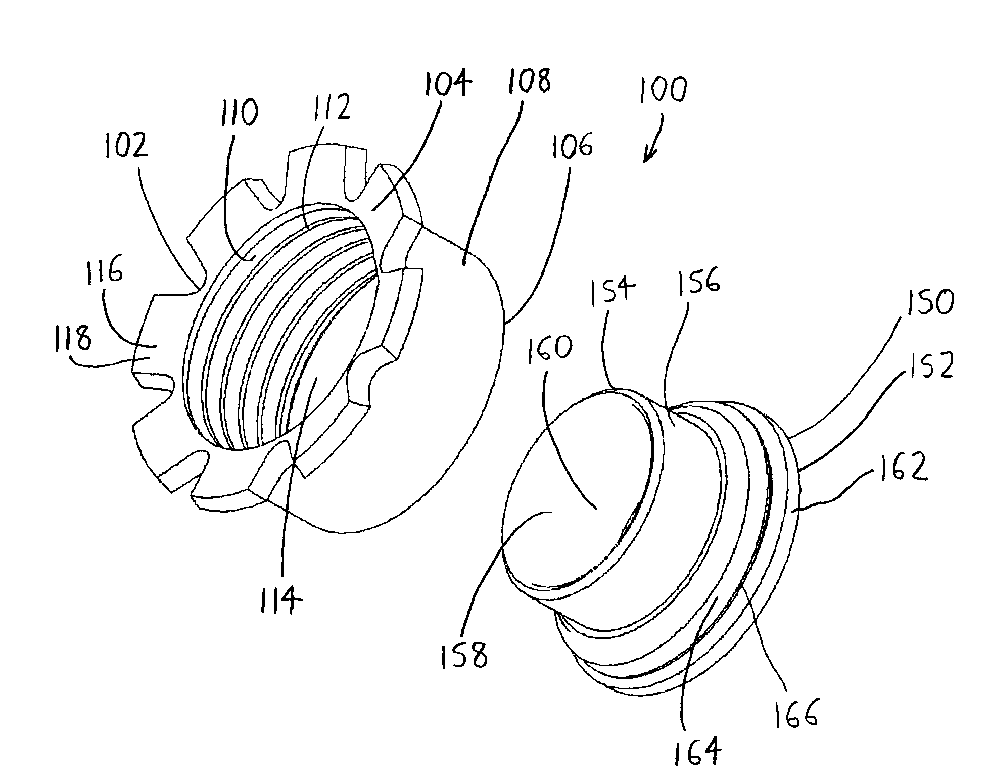
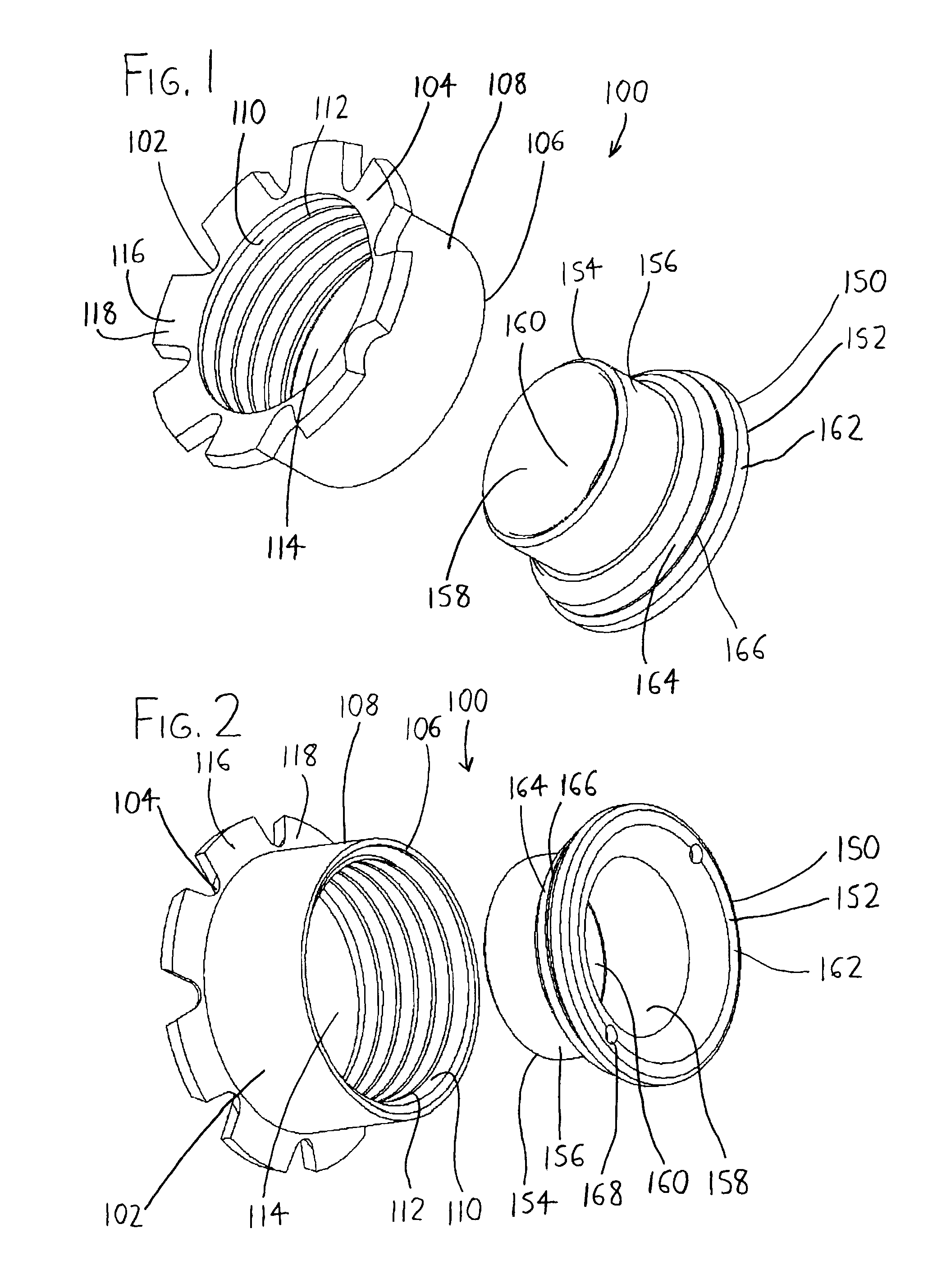
[0018]Referring particularly to FIG. 5 to assist in visualizing the invention, the connector assembly 100 may be installed in the junction box 200 in the following manner. Initially, the male connector 130 may have its threaded connector junction end 138 inserted into the box wall passage 206 of the junction box 200 by some desired amount. In this respect, the exemplary male connector 130 of FIG. 5 is shown with an insertion flange 144 next to its connector junction end 138, with the insertion flange 144 limiting insertion of the junction end 138 into the box wall passage 206 (i.e., the connector junction end 138 may be inserted into the box wall passage 206 until the insertion flange 144 interferes with the box wall 202). The nut 102 may then be threaded onto the connector junction end 138, with the connector junction end 138 being received within the inner nut passage 114 to engage the nut threading 112 on the inner nut surface 110 (best seen in FIG. 3). As this is done, the box w...


PUM


Abstract

A connector / bushing assembly for electrical junction boxes includes a nut which may receive a male conduit / connector which extends through the wall of a junction box, and a liner situated within the nut. The nut receives the male connector within a nut junction end situated opposite from a nut entry end. The liner is received within the nut entry end to extend toward the nut junction end, and includes a floating portion near the nut junction end, with the floating portion defining a cylinder spaced from the inner diameter of the nut junction end so that the (cylindrical) male connector can be received within the nut junction end between the floating portion and the nut junction end.

Description

FIELD OF THE INVENTION[0001]The invention relates generally to fittings or connectors for conduits, such as pipes, tubes, ducts, and the like, and it relates more particularly to connector assemblies for joining electrical conduits.BACKGROUND OF THE INVENTION[0002]In the electrical trade, junction boxes—small boxes / compartments made of plastic or other materials, with at least one open wall and having entries / apertures defined in other walls—are often installed in buildings at points where electrical wires and / or other cables are to be connected to components such as sockets, switches, outlets, and / or other wires. A junction box is installed at the point where the connection is desired, usually within the building wall or ceiling, by nailing or screwing the junction box to a stud within the wall or ceiling. Cable is then brought to the junction box and extended through a passage in a junction box wall to enter the junction box interior.[0003]In some cases, it is useful to protect th...

Claims


Application Information

Patent Timeline
IPC IPC(8): H02G3/18
CPCH02G3/0666H02G3/088H02G3/0675Y10T16/063
Inventor SHEMTOV, SAMI
Owner ATKORE STEEL COMPONENTS INC
Features
  • Generate Ideas
  • Intellectual Property
  • Life Sciences
  • Materials
  • Tech Scout
  • Unparalleled Data Quality
  • Higher Quality Content
  • 60% Fewer Hallucinations
Learn More