System and method for assigning analysis parameters to vision detector using a graphical interface

a graphical interface and analysis parameter technology, applied in the field of automatic detection and inspection, can solve the problems of difficult to arrange the photodetectors, the simple sensing of light intensity reflected from a point on the object is often insufficient for inspection, and the use of automatic inspection using photodetectors

Active Publication Date: 2009-12-22
COGNEX TECH & INVESTMENT
View PDF49 Cites 30 Cited by
  • Summary
  • Abstract
  • Description
  • Claims
  • Application Information

AI Technical Summary

Benefits of technology

[0109]This invention provides a system and method for automating the setup of Locators and Detectors within an image view of an object on the HMI of a vision detector by determining detectable edges and best fitting the Locators and Detectors to a location on the object image view following the establishment of an user selected operating point on the image view, such as by clicking a GUI cursor. In this manner, the initial placement and sizing of the graphical elements for Locator and Detector ROIs are relatively optimized without excessive adjustment by the user. Locators can be selected for direction, including machine or line-movement direction, cross direction or angled direction transverse to cross direction and movement direction. Detectors can be selected based upon particular analysis tools, including brightness tools, contrast tools and trained templates. The Locators and detectors are each associated with a particular set of operating parameters, such as activation threshold, which are displayed in a control box within the GUI (and can be accessed by clicking on the specific Locator or Detector. A parameter bar can also be provided adjacent to the depiction of the Detector on the image view for easy reference. Both Locators and Detectors may be manually readjusted once automatically placed and sized by drag and drop techniques.
[0111]The automatic placement process is constructed and arranged to place the Locator on the image view relative to a nearest adjacent edge of the image view and to adjust the Locator so as to avoid a stronger-magnitude more-distant edge. This allows a Locator having a predetermined width when originally sized to be finally sized with a cutoff on the side near the stronger edge, thus avoiding confusion as the object moves through the field of view between edges, since the Locator's activation threshold is generally set relative to the nearest adjacent edge's magnitude.

Problems solved by technology

Automatic inspection using photodetectors has various disadvantages, however, including:
Simple sensing of light intensity reflected from a point on the object is often insufficient for inspection.
For example, to detect an edge it may be necessary to analyze a pattern of brightness to see if it corresponds to a transition from a lighter to a darker region.It may be hard to arrange the photodetectors when many points on an object need to be inspected.
This requirement may add additional cost and complexity that can offset the low cost and simplicity of the photodetectors.
Machine vision systems have disadvantages compared to an arrangement of photodetectors, including:They are relatively expensive, often costing ten times more than an arrangement of photodetectors.They can be difficult to set up, often requiring people with specialized engineering training.They operate much more slowly than an arrangement of photodetectors, typically requiring tens or hundreds of milliseconds to make a decision.
Furthermore, the decision time tends to vary significantly and unpredictably from object to object.
Machine vision systems have limitations that arise because they make decisions based on a single image of each object, located in a single position in the field of view (each object may be located in a different and unpredictable position, but for each object there is only one such position on which a decision is based).
The use of only a single perspective often leads to incorrect decisions.
It has long been observed, for example, that a change in perspective of as little as a single pixel can in some cases change an incorrect decision to a correct one.
Also, the limitations of machine vision systems arise in part because they operate too slowly to capture and analyze multiple perspectives of objects in motion, and too slowly to react to events happening in the field of view.
If a Photo is linked to two nearly parallel Locators, its motion would be unstable.

Method used


Image

  • System and method for assigning analysis parameters to vision detector using a graphical interface
  • System and method for assigning analysis parameters to vision detector using a graphical interface
  • System and method for assigning analysis parameters to vision detector using a graphical interface

Examples


Embodiment Construction

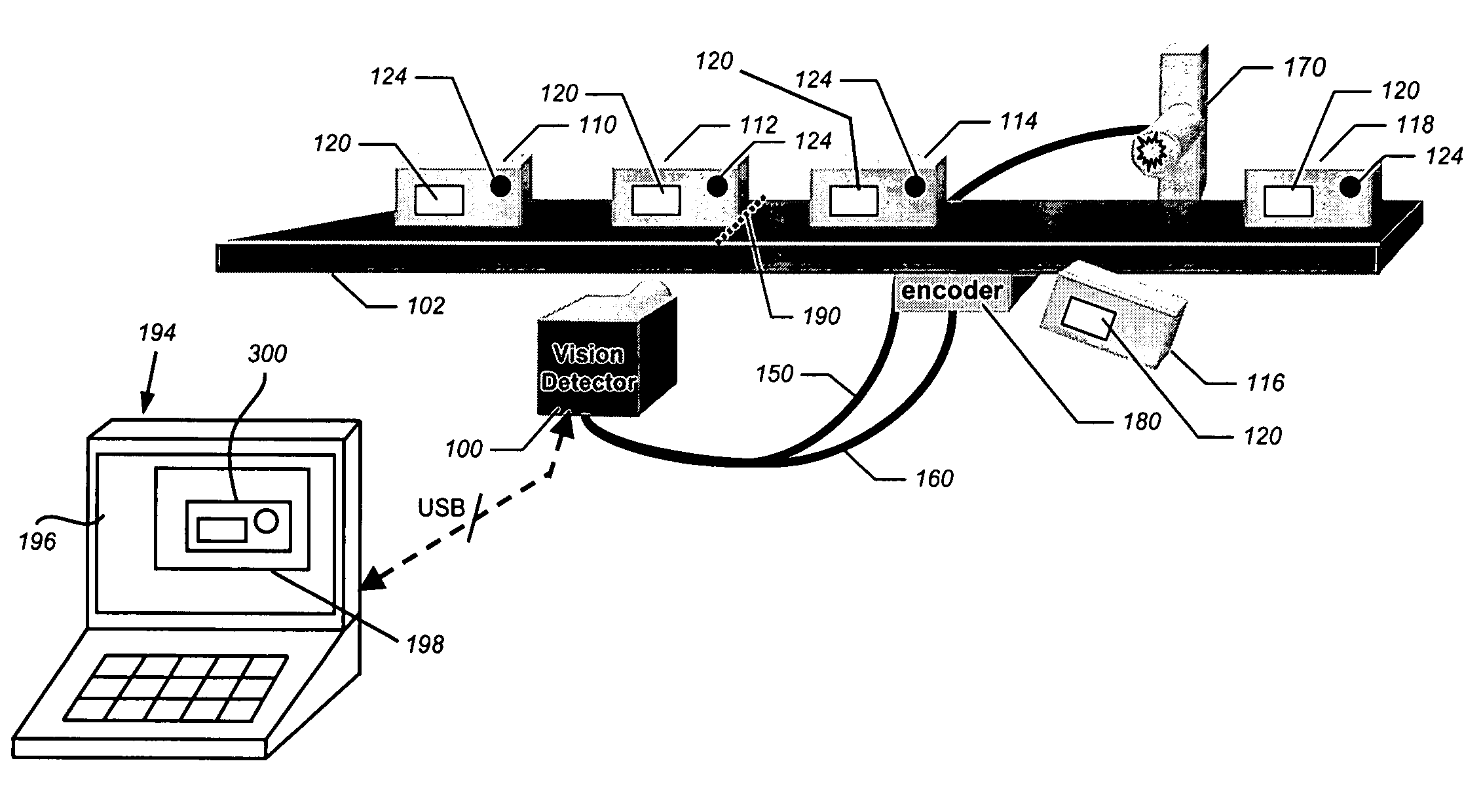
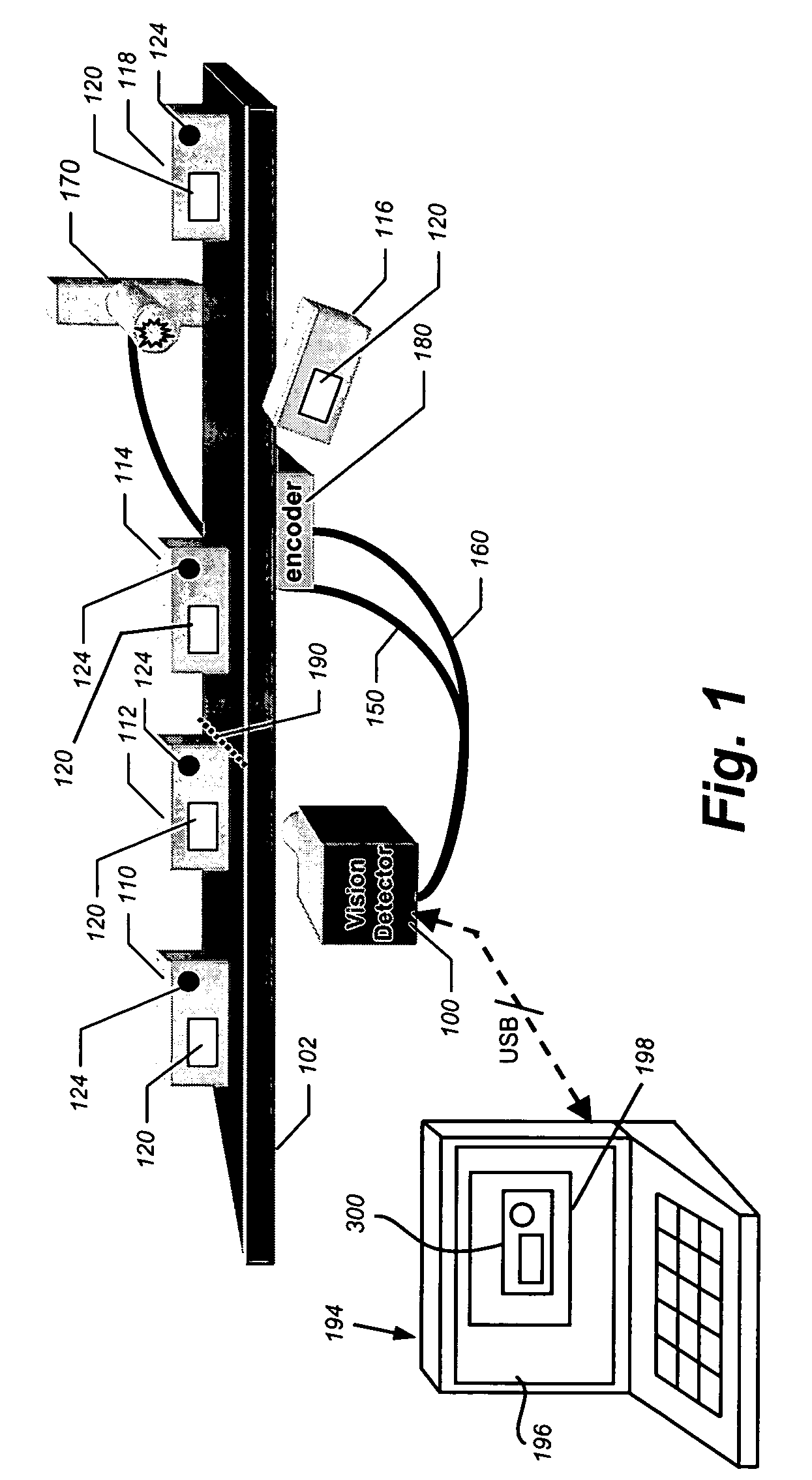
[0142]FIG. 18 shows a diagram of a Graphical User Interface (GUI) screen 1800 for a Human-Machine Interface (HMI), interconnected with a vision detector (100) like that shown and described with reference to FIG. 1 above and in connection with the above-incorporated-by-reference METHOD AND APPARATUS FOR VISUAL DETECTION AND INSPECTION OF OBJECTS, by William M. Silver. The screen can reside on any acceptable HMI, including, but not limited to an Laptop Personal Computer (PC); Desktop PC, personal digital assistant or Notebook Computer (for example PC 194) having an appropriate communication link (e.g. USB, wireless, network cable, etc.) with the vision detector (100). An appropriate HMI interface (described in connection with the above-incorporated-by-reference METHOD AND APPARATUS) interconnects with the vision detector's DSP to allow communication with the FMI. Note that the layout and menu contents of the illustrated screen 1800 is exemplary, and a variety of layouts and menu items...


PUM


Abstract

This invention provides a system and method for automating the setup of Locators and Detectors within an image view of an object on the HMI of a vision detector by determining detectable edges and best fitting the Locators and Detectors to a location on the object image view following the establishment of an user selected operating point on the image view, such as by clicking a GUI cursor. In this manner, the initial placement and sizing of the graphical elements for Locator and Detector ROIs are relatively optimized without excessive adjustment by the user. Locators can be selected for direction, including machine or line-movement direction, cross direction or angled direction transverse to cross direction and movement direction. Detectors can be selected based upon particular analysis tools, including brightness tools, contrast tools and trained templates. The Locators and detectors are each associated with a particular set of operating parameters, such as activation threshold, which are displayed in a control box within the GUI (and can be accessed by clicking on the specific Locator or Detector. A parameter bar can also be provided adjacent to the depiction of the Detector on the image view for easy reference. Both Locators and Detectors may be manually readjusted once automatically placed and sized by drag and drop techniques.

Description

RELATED APPLICATION[0001]This application is related to copending and commonly assigned U.S. patent application Ser. No. 10 / 865,155, entitled METHOD AND APPARATUS FOR VISUAL DETECTION AND INSPECTION OF OBJECTS, by William M. Silver, filed Jun. 9, 2004, the teachings of which are expressly incorporated herein by reference.FIELD OF THE INVENTION[0002]This invention relates to automated detection and inspection of objects being manufactured on a production line, and more particularly to setup systems and methods for such automated detection and inspection.BACKGROUND OF THE INVENTION[0003]Industrial manufacturing relies on automatic inspection of objects being manufactured. One form of automatic inspection that has been in common use for decades is based on optoelectronic technologies that use electromagnetic energy, usually infrared or visible light, photoelectric sensors, and some form of electronic decision making.[0004]One well-known form of optoelectronic automatic inspection uses ...

Claims


Application Information

Patent Timeline
Patent Type & Authority Patents(United States)
IPC IPC(8): G06K9/00
CPCG06F9/4443G06F3/0481G06F9/451
Inventor MIRTICH, BRIAN V.EAMES, ANDREWPHILLIPS, BRIAN S.TREMBLAY, II, ROBERT J.KEATING, JOHN F.WHITMAN, STEVEN
Owner COGNEX TECH & INVESTMENT
Why Eureka
Try Eureka