QAM optical modulators

a technology of optical modulators and optical phase shifters, applied in optics, instruments, electrical equipment, etc., can solve the problems of low spectral efficiency of techniques and complicated implementation of optical phase shifters

Active Publication Date: 2009-12-22
RPX CORP +1
View PDF2 Cites 17 Cited by
  • Summary
  • Abstract
  • Description
  • Claims
  • Application Information

AI Technical Summary

Problems solved by technology

While high transmission rate can be achieved by multiplexing a data stream onto different optical channels in parallel, this simple technique tends to provide a low spectral efficiency.
Nevertheless, some such optical phase shifters are complicated to implement due to nonlinearities and / or weak electro-optical responses.

Method used


Image

  • QAM optical modulators
  • QAM optical modulators
  • QAM optical modulators

Examples


example 1

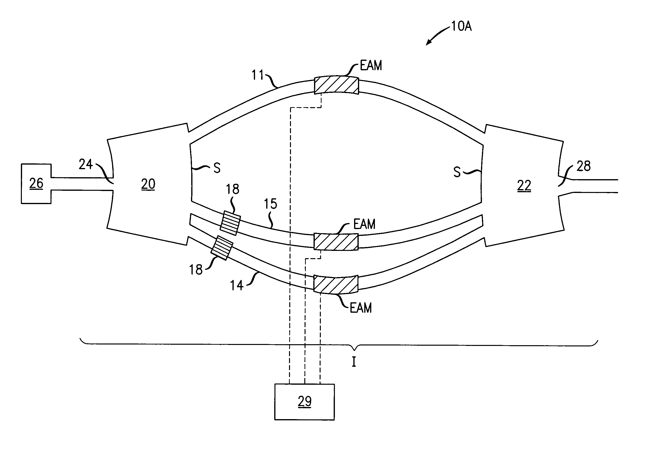
[0060]First exemplary embodiments of the optical modulators 10C-10D set internal light amplitudes and relative phases between interfered light as described below. With respect to internal light amplitudes, each controllable optical waveguide 12, 15 of a first group is configured to transmit a maximum light amplitude to the optical output 28 of the output optical coupler 22 that is about twice the maximum light amplitude transmitted thereto by each controllable optical waveguide 11, 14 of a second group. For example, in their ON or substantially transmitting states, a ratio of the light amplitude transmitted to the optical output 28 of the output optical coupler 22 by the individual controllable optical waveguides 12, 15 of the first group over the light amplitude transmitted thereto by the individual controllable optical waveguides 11, 14 of the second group may be in the interval [1.5, 2.5] and preferably is in the interval [1.8, 2.2]. The differences in maximum light amplitudes tr...

example 2

[0064]Second exemplary embodiments of the optical modulators 10C-10D set internal light amplitudes and relative phases between interfered light as described below. With respect to light amplitudes, the controllable optical waveguides 11, 12, 14, 15 transmit, i.e., in their ON states or substantially transmitting states, maximum light amplitudes to the optical output 28 of the output optical coupler 22 whose ratios have the values described above for the first exemplary embodiments. With respect to relative phases, light from the low power controllable optical waveguides 11, 14 interferes at the optical output 28 of the output optical coupler 22 with a first relative phase of about 90 degrees. Also, light from the high power controllable optical waveguides 15, 12 interferes at the optical output 28 of the output optical coupler 22 with a second relative phase of about 90 degrees. For example, the first and second relative phases may be in the range of 90°±20° and preferably are in th...


PUM

PropertyMeasurementUnit
lengthaaaaaaaaaa
thicknessaaaaaaaaaa
compressive strainaaaaaaaaaa

Abstract

An exemplary optical modulator includes an interferometer. The interferometer includes an input optical coupler, an output optical coupler, and two or more controllable optical waveguides. Each controllable optical waveguide connects the input optical coupler to the output optical coupler and has an electro-absorption modulator along a segment thereof. Two of the controllable optical waveguides are connected to transmit to an output of the output optical coupler light of substantially different maximum amplitude.

Description

BACKGROUND[0001]1. Field of the Invention[0002]The invention relates generally to optical transmission apparatus and methods and more particularly, to optical modulators and optical modulation methods.[0003]2. Discussion of the Related Art[0004]This section introduces aspects that may help facilitate a better understanding of the inventions. Accordingly, the statements of this section are to be read in this light and are not to be understood as admissions about what is prior art or what is not prior art.[0005]There is a strong interest in optical communication systems that transmit data at high rates. While high transmission rate can be achieved by multiplexing a data stream onto different optical channels in parallel, this simple technique tends to provide a low spectral efficiency. The spectral efficiency may be increased by relying on larger symbol constellations to modulate the data stream onto the optical carrier, e.g., a quadrature phase shift keyed (QPSK) constellation. Some ...

Claims


Application Information

Patent Timeline
Patent Type & Authority Patents(United States)
IPC IPC(8): G02F1/035
CPCG02F1/2257H04B10/5053G02F2001/0155G02F2202/108G02F2001/212G02F1/0155G02F1/212
Inventor DOERR, CHRISTOPHER RICHARDWINZER, PETER J.
Owner RPX CORP
Why Eureka
Try Eureka