Multiple use handle support for distributing forces

a multi-use, handle technology, applied in multi-purpose tools, handbags, manufacturing tools, etc., can solve the problems of affecting the effectiveness of prior art devices, affecting the use of users, and affecting the use of the device, so as to achieve convenient holding

Inactive Publication Date: 2009-12-29
ADVANCE HANDLE
View PDF28 Cites 26 Cited by
  • Summary
  • Abstract
  • Description
  • Claims
  • Application Information

AI Technical Summary

Benefits of technology

[0007]The handle support of this invention may be molded or cast from a light weight material such as plastic or aluminum, or other suitable material. It has a series of integrally formed sections extending from a forward end to a rearward end. The forward end forms an attachment post to which some sort of a tool is removably secured by appropriate means. A grip portion extends downward from the attachment post at an angle to allow the grip to be conveniently held by the user's hand. In the preferred embodiment, a generally planar seat portion, which may be contoured to the shape of the wrist, extends rearward from the grip portion at an obtuse angle to form a forward leaning Z-shaped front end to the handle support of this invention. A brace portion extends rearward from the planar seat in a helical form which varies in pitch and increases in radius of curvature from front to rear. The brace portion thereby circumscribes an open space which is substantially conical in form. The handle support of this invention, therefore, includes a portion which forms a helical wrap for engagement with the arm and a portion which allows the removable attachment of a variety of tools. In this manner forces, exerted by or on the hand and wrist, are distributed over the interior surface of the helical brace portion as needed.

Problems solved by technology

It is common knowledge that when so used, such devices place a great deal of strain on the hand and wrist of the user.
Torsional, lateral and axial forces must be transmitted from the hand and wrist to the device, causing awkwardness, fatigue, and sometimes injury.
The efficacy of the prior art devices is generally defeated by the varying size and structure of the user, the diversity of stresses distributed to and from the tool, or discomfort experienced by the user.
In addition, there is generally difficulty in installing the support on the forearm, which often requires the use of the other hand.
Such devices are difficult to use effectively with one hand.

Method used


Image

  • Multiple use handle support for distributing forces
  • Multiple use handle support for distributing forces
  • Multiple use handle support for distributing forces

Examples


Embodiment Construction

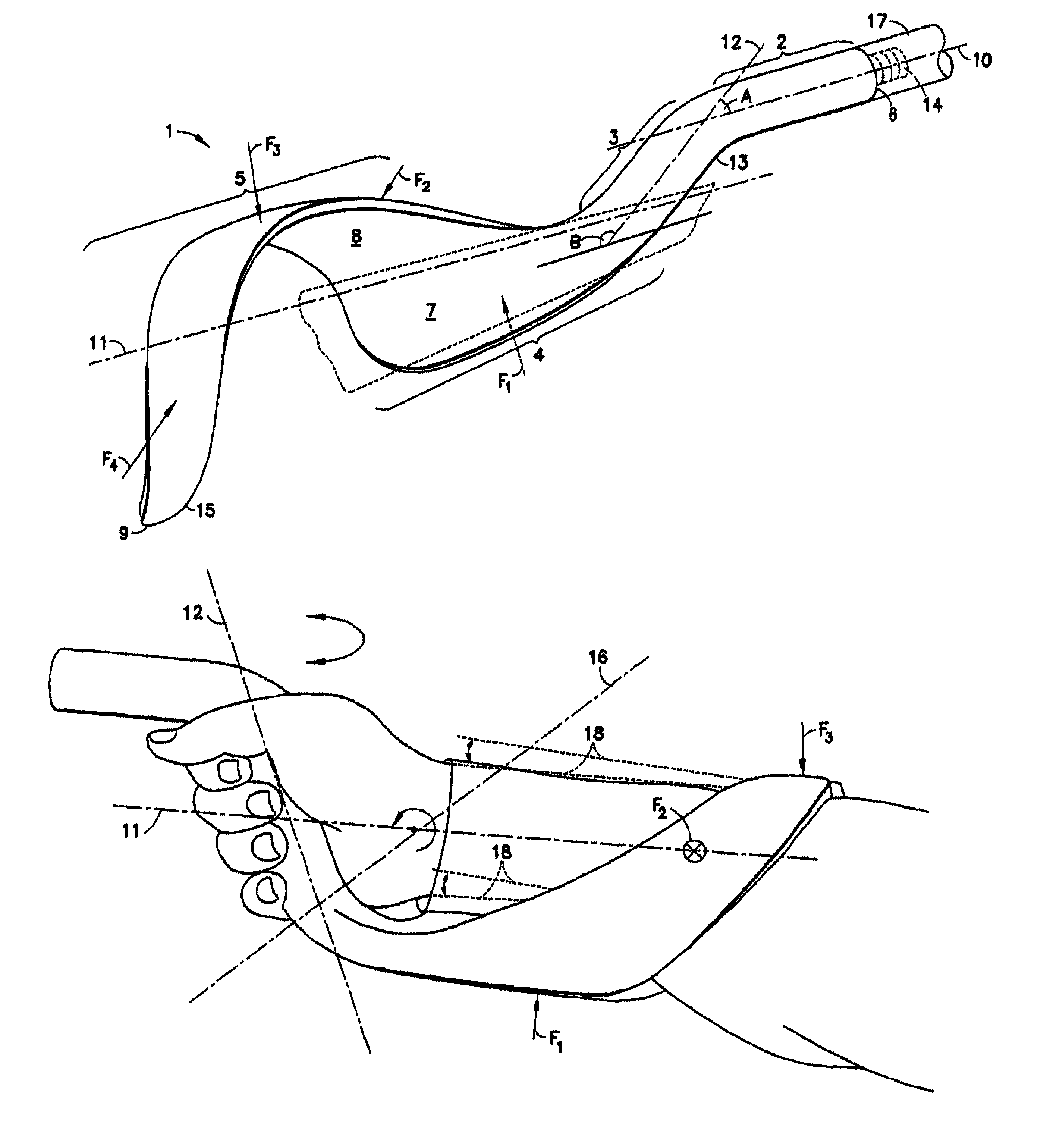
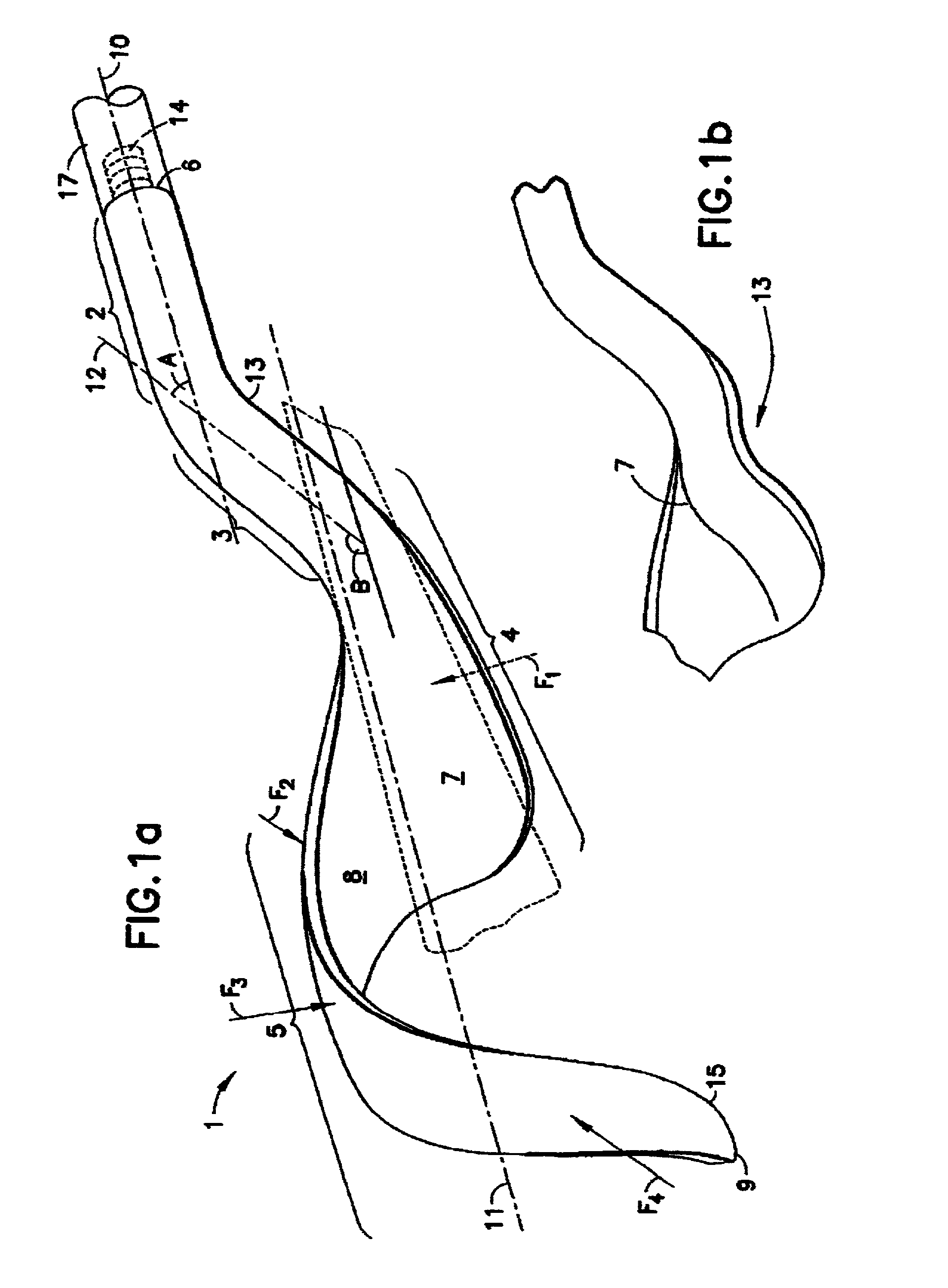
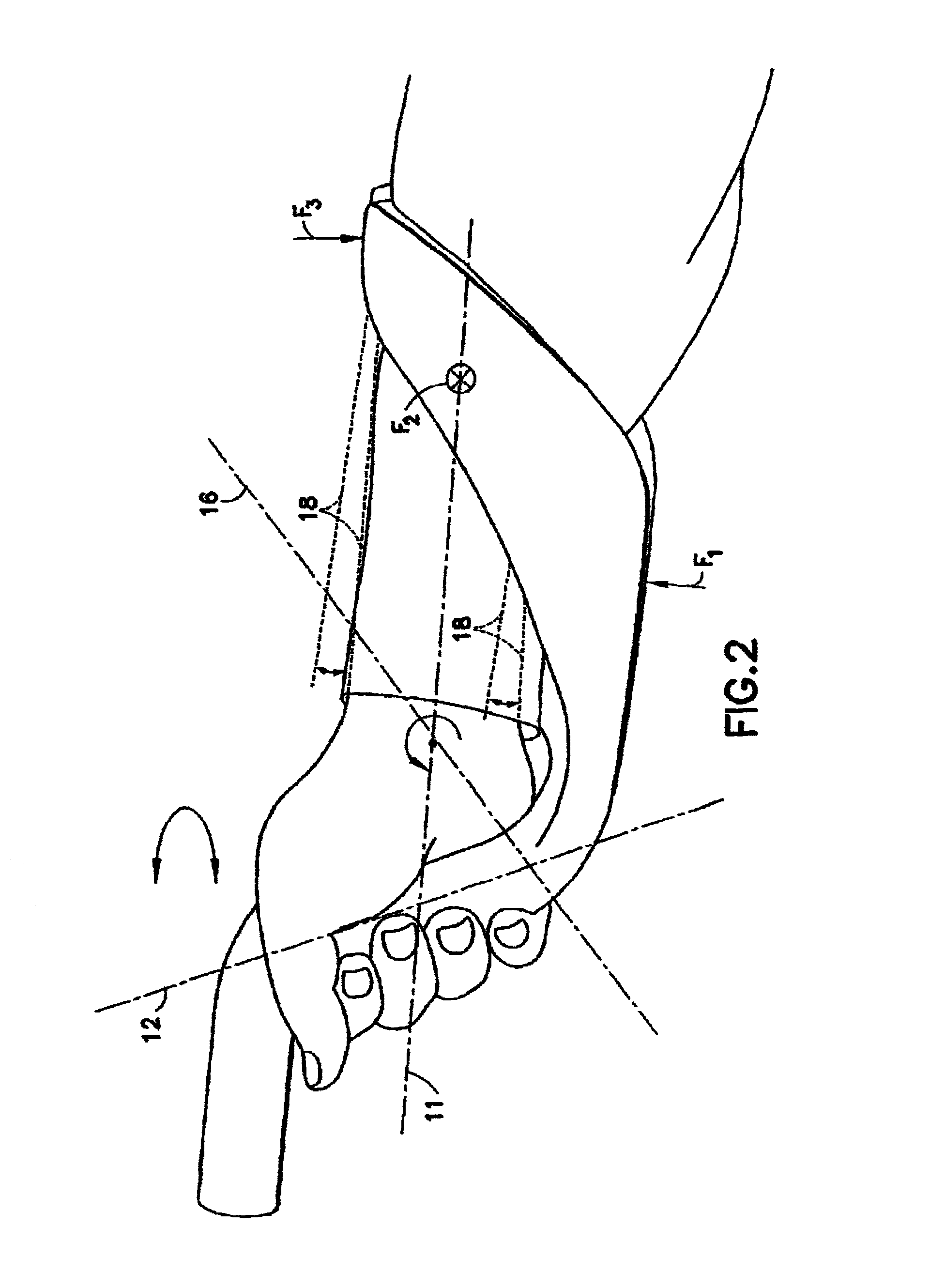
[0016]As shown in FIG. 2, the handle support of this invention is a cast or molded, one piece rigid device constructed of a strong plastic material or light weight metal, such as aluminum. It has a uniquely contoured body 1 extending from a forward end 6 in front of the hand of the user to a rearward end 9 near the elbow of the user. Body 1 is integrally formed of multiple sections. At its forward end 6 there is an attachment post 2 which extends rearward. The attachment post 2 may be a generally elongated cylindrically shaped section to which is fixed a coupling mechanism 14 at the forward most end 6. The coupling mechanism is designed to facilitate the attachment of the attachment post 2 to a shaft 17 of a tool (not shown). The coupling mechanism 14 could be a variety of configurations from a simple male fitting with coarse threads, as shown in FIG. 1a, to a female receptacle with a compression nut, to a keyless chock, or a special purpose chock, depending on the tool or appliance...


PUM


Abstract

A handle support is constructed for removable attachment to, a tool, appliance or other implement for hand held use. The handle support includes a brace portion extending rearward in a helical form. The brace portion circumscribes an open space which is substantially conical in form.

Description

RELATED APPLICATIONS[0001]This application is a conversion of provisional application Ser. No. 60 / 345,688, filed Dec. 31, 2001 and of earlier filed provisional application Ser. No. 60 / 286,436 filed, Apr. 26, 2001.BACKGROUND OF THE INVENTION[0002]Many tools and appliances are used while being supported by one hand of the user. Such tools as brushes, paint rollers, window squeegees, scrapers, spray wands, certain brooms, shovels, rakes and the like, use elongated poles as part of their structure. It is common knowledge that when so used, such devices place a great deal of strain on the hand and wrist of the user. The long lever action of such tools amplifies the force required to be exerted by the hand and wrist of the user in order to exert a force at the working end. Torsional, lateral and axial forces must be transmitted from the hand and wrist to the device, causing awkwardness, fatigue, and sometimes injury.[0003]The prior art is replete with efforts to distribute the forces expe...

Claims


Application Information

Patent Timeline
Patent Type & Authority Patents(United States)
IPC IPC(8): A61F5/00B25G1/00B25G1/10B25G3/32A01B1/00A61H3/02
CPCA01B1/00B25G1/102A45F2005/008A61H3/02Y10T16/476Y10T16/4713Y10T16/469
Inventor CARMAN, JR., EDWARD C.CARMAN, III, EDWARD C.
Owner ADVANCE HANDLE
Why Eureka
Try Eureka