Protective relay device, system and methods for Rogowski coil sensors

a relay device and coil sensor technology, applied in the field of electric power systems, can solve problems such as high equipment costs

Active Publication Date: 2009-12-29
EATON INTELLIGENT POWER LTD
View PDF51 Cites 25 Cited by
  • Summary
  • Abstract
  • Description
  • Claims
  • Application Information

AI Technical Summary

Problems solved by technology

Such equipment is expensive, and each piece of equipment typically plays a vital role in the distribution of power to end users, such that an outage caused by the equipment being damaged or taken out of service for repair or replacement, may have costly consequences.
As a result, such equipment is typically protected from potentially damaging overvoltages and overcurrents by protective components, such as relay devices that open and close portions of the system in response to actual operating conditions.

Method used


Image

  • Protective relay device, system and methods for Rogowski coil sensors
  • Protective relay device, system and methods for Rogowski coil sensors
  • Protective relay device, system and methods for Rogowski coil sensors

Examples


Embodiment Construction

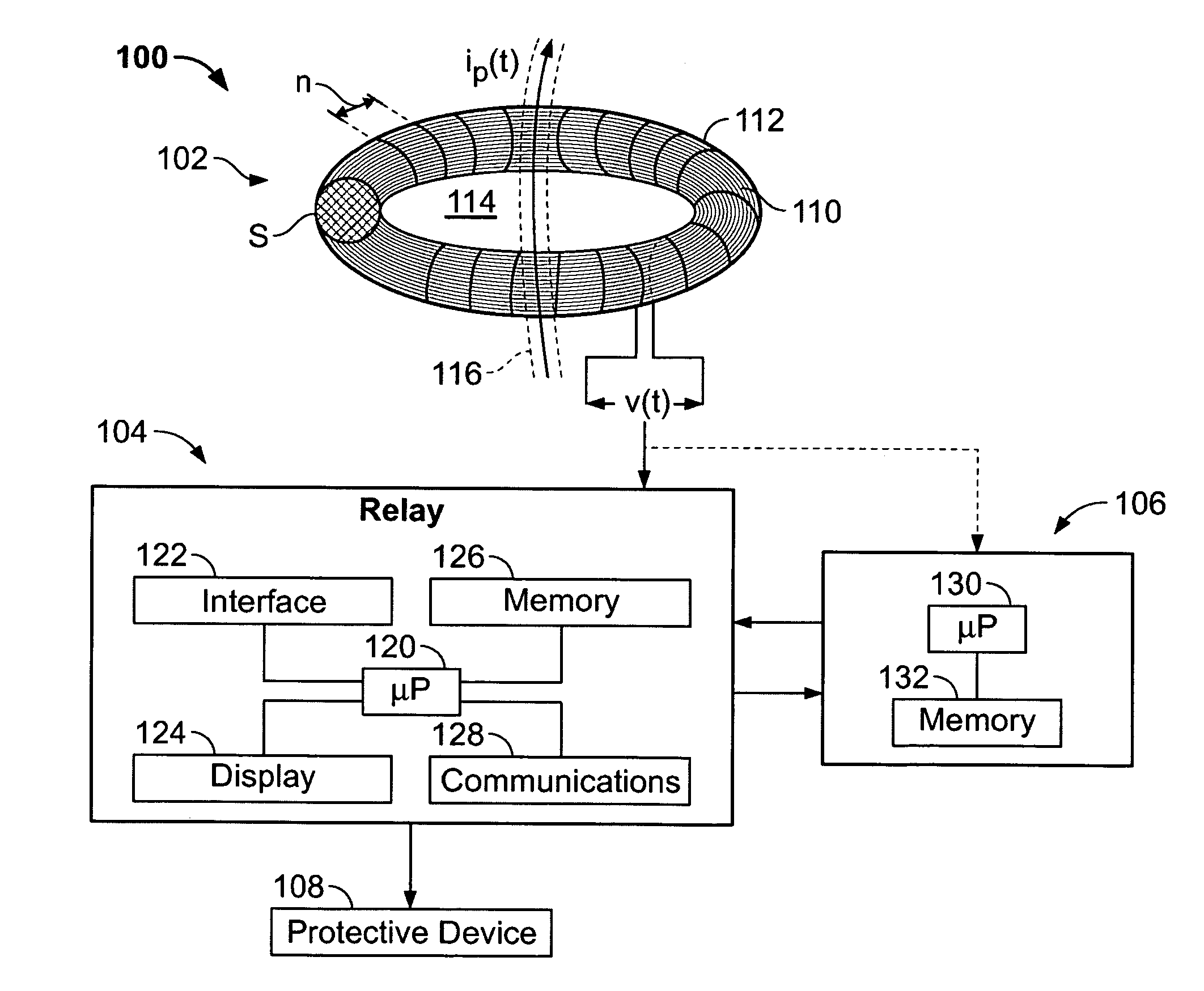
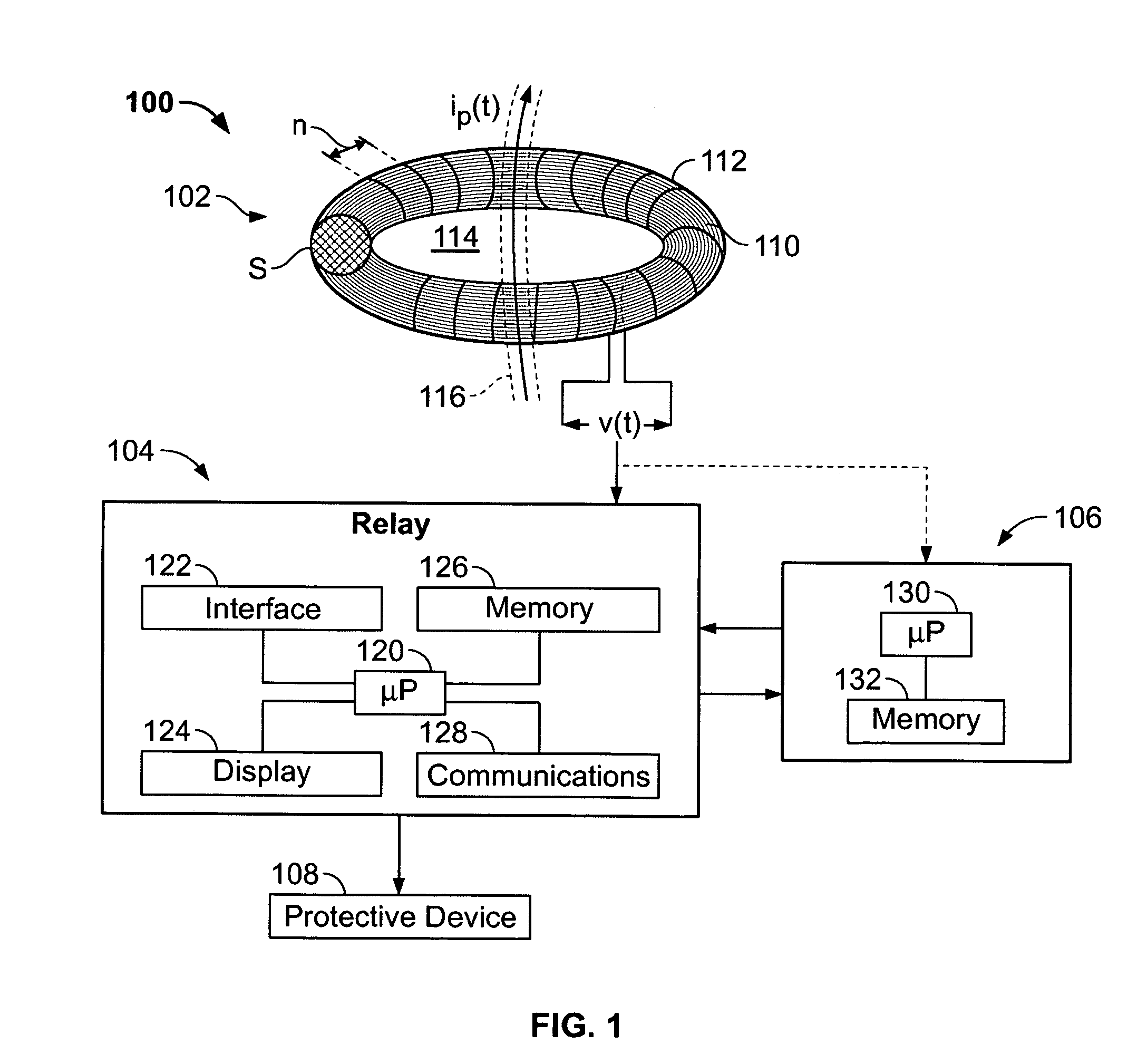
[0035]Successful operation of network protection devices in an electrical power system is of course dependent upon accurate sensing and measurement of operating conditions. Microprocessor based equipment, such as digital relay devices, are increasingly being used in electrical power systems, and complex signal processing issues are raised, especially for phasor based relay systems, to provide input data to the relay devices for making control decisions.

[0036]In existing electrical power systems for electric utility companies and industrial facilities, current transformers (CTs) are utilized for measuring operation conditions of the system. The transformers may be connected to network protection devices, such as protective relays and circuit breakers, and signal outputs from the current transformers are input to the protective devices and are used to make control decisions by the network protection devices to open circuitry when fault conditions are detected, thereby protecting the p...


PUM


Abstract

Relay devices, systems and methods for obtaining an accurate representation of a current monitored with a Rogowski coil, without integration of the Rogowski coil output voltage signal in the time domain.

Description

BACKGROUND OF THE INVENTION[0001]This invention relates generally to electrical power systems, and more specifically to protective relay systems and controls therefor.[0002]Electrical generation and power transmission networks include a large number of transformers, capacitor banks, reactors, motors, generators and other major pieces of electrical equipment. Such equipment is expensive, and each piece of equipment typically plays a vital role in the distribution of power to end users, such that an outage caused by the equipment being damaged or taken out of service for repair or replacement, may have costly consequences. As a result, such equipment is typically protected from potentially damaging overvoltages and overcurrents by protective components, such as relay devices that open and close portions of the system in response to actual operating conditions.BRIEF DESCRIPTION OF THE DRAWINGS[0003]FIG. 1 schematically illustrates a protective relay system according to the present inve...

Claims


Application Information

Patent Timeline
Patent Type & Authority Patents(United States)
IPC IPC(8): G01R15/18
CPCH02H1/0007G01R15/181
Inventor KOJOVIC, LJUBOMIR A.WILLIAMS, STEPHEN E.
Owner EATON INTELLIGENT POWER LTD
Why Eureka
Try Eureka