Circuit and method for suppressing gate induced drain leakage

a technology of gate induced drain and circuit, applied in pulse generators, pulse techniques, instruments, etc., can solve problems such as the increase of leakage to operating curren

Active Publication Date: 2009-12-29
POLARIS INNOVATIONS LTD
View PDF8 Cites 11 Cited by
  • Summary
  • Abstract
  • Description
  • Claims
  • Application Information

AI Technical Summary

Problems solved by technology

Thus, as devices with smaller and smaller feature sizes are developed, the ratio of leakage to operating current increases.

Method used


Image

  • Circuit and method for suppressing gate induced drain leakage
  • Circuit and method for suppressing gate induced drain leakage
  • Circuit and method for suppressing gate induced drain leakage

Examples


Embodiment Construction

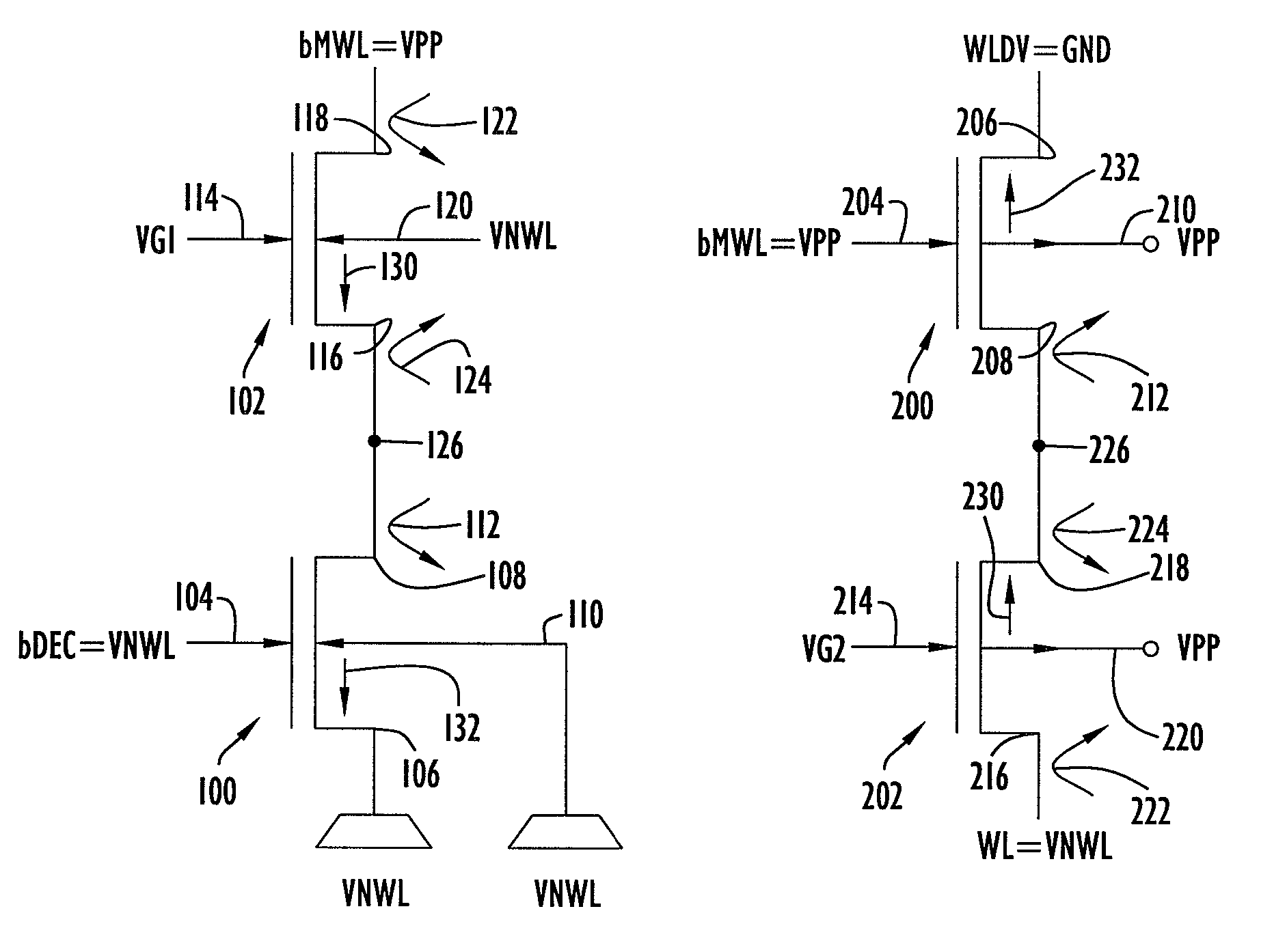
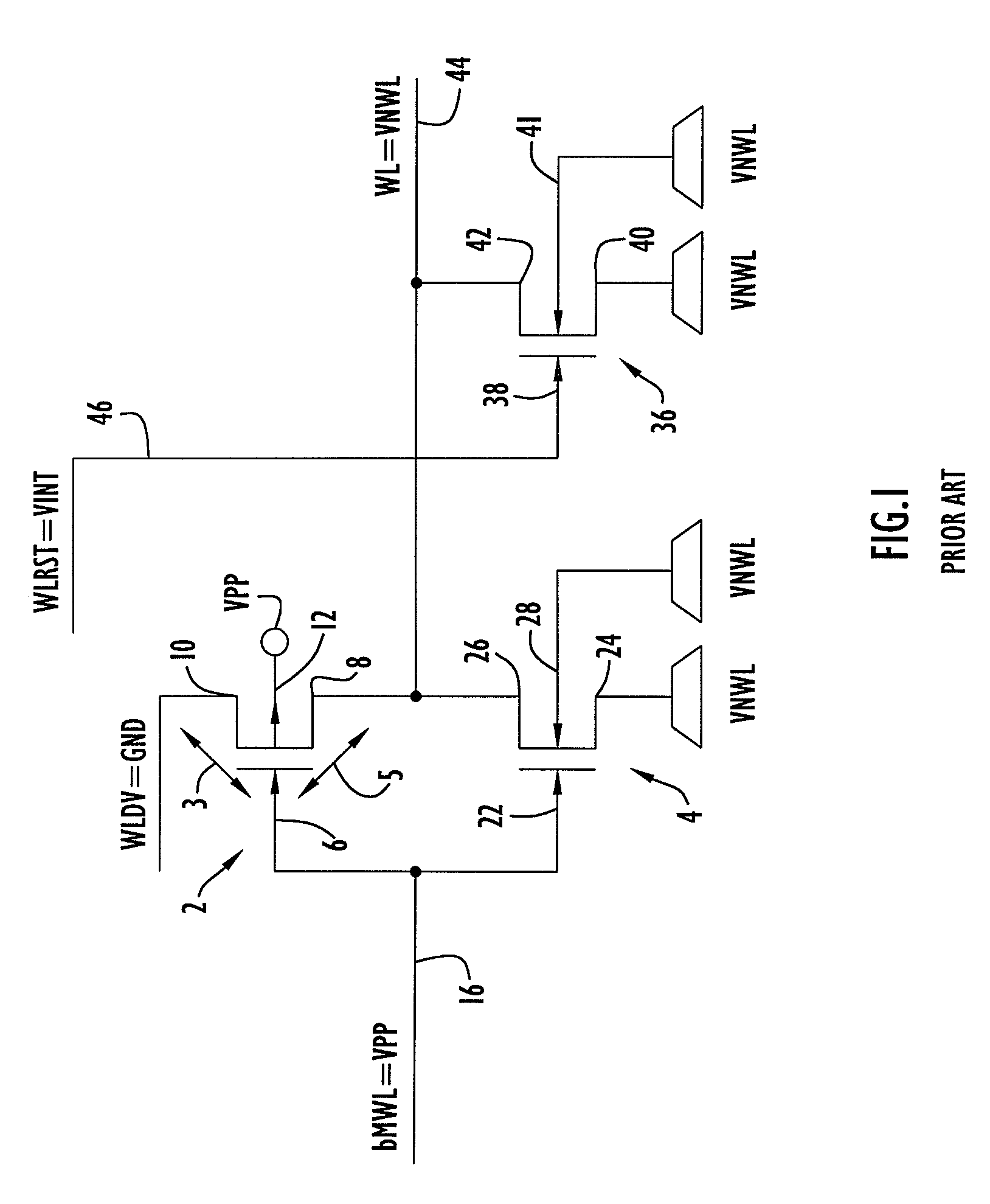
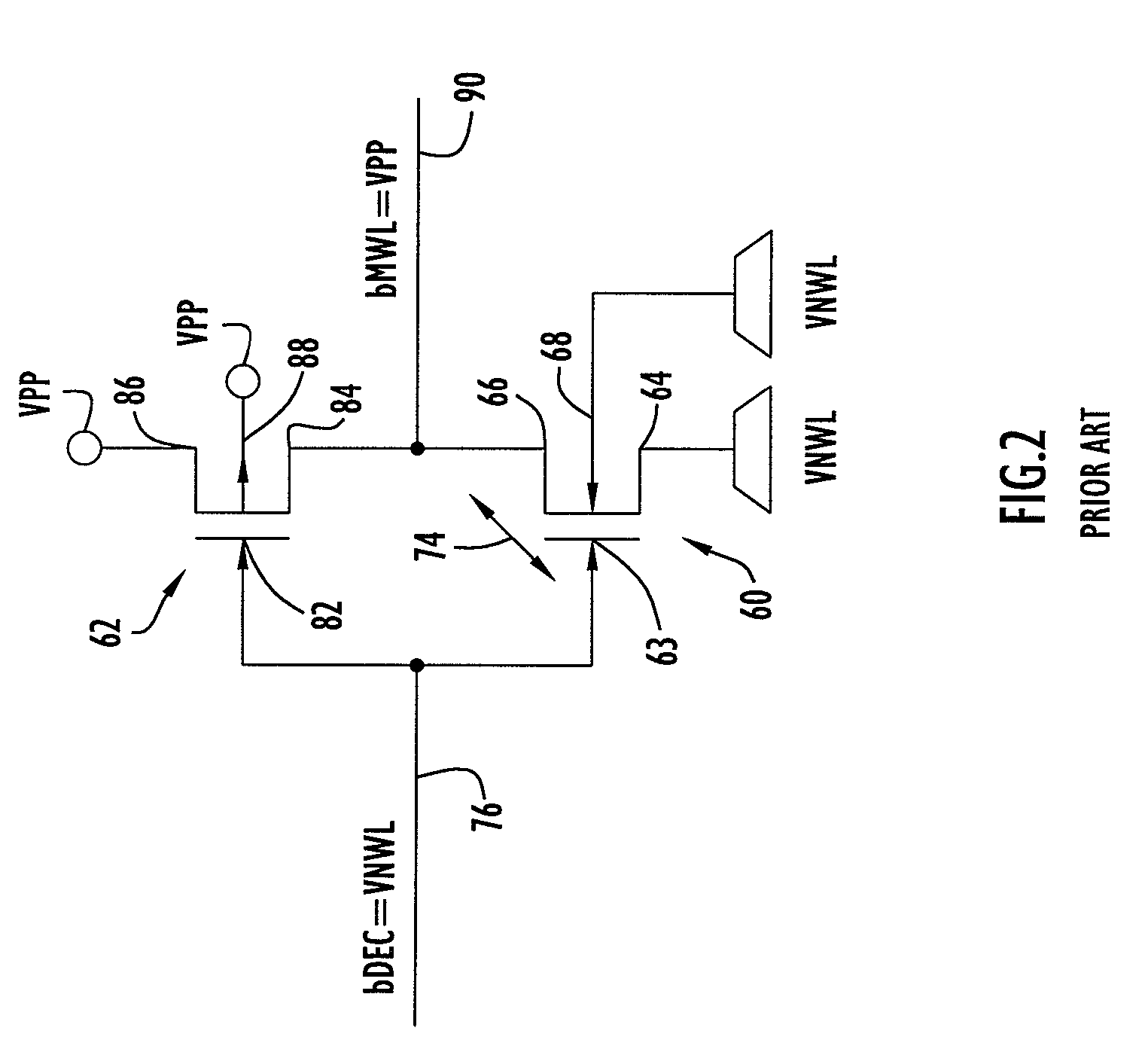
[0013]FIG. 1 depicts a prior art wordline driver for a DRAM while FIG. 2 depicts a prior art master wordline driver for a DRAM. For clarity of illustration, the invention is described in connection with a particular application, a wordline driver for a DRAM, but it should be understood that the invention is broadly applicable to any application involving FET circuitry.

[0014]In memory arrays it may be desirable to access an entire row (or column) at once rather than each memory cell individually. Due to gate capacitance and wire load restrictions a whole row (or column) of cells cannot be driven by one wordline driver, instead a segmented approach is chosen. Referring again to FIGS. 1 and 2, a master wordline driver, such as is shown in FIG. 2 is used in the accessing of the segmented wordline driver of FIG. 1 which is used in accessing individual words which comprise the row.

[0015]Referring to FIG. 1, the circuit depicted is an inverting complementary MOSFET (CMOS) wordline driver. ...


PUM


Abstract

An electrical circuit comprising a first metal oxide silicon (MOS) n type field effect transistor (NFET) or p type field effect transistor (PFET) and a second MOS NFET or PFET of the same conductivity type as the first NFET or PFET, wherein the drain of the first NFET or PFET is directly connected to the source of the second NFET or PFET, and wherein the gate of the second NFET or PFET is at a voltage value which is equal to or lower than the drain voltage value of the second NFET or PFET in the case of an NFET and equal to or higher than the drain voltage value of the second NFET or PFET in the case of a PFET.

Description

FIELD OF THE INVENTION[0001]The present invention is directed to a circuit and method for suppressing gate induced drain leakage (GIDL) in field effect transistors (FETs).BACKGROUND OF THE INVENTION[0002]Field effect transistors are widely used in electronic circuitry. It is desirable to keep leakage currents in such devices as low as possible or eliminate them altogether, since such currents waste power. One leakage mechanism which results in a relatively small amount of leakage in metal oxide silicon (MOS) type field effect transistors (MOSFETs) is known as gate induced drain leakage (GIDL). In the prior art, because of the small amount of leakage involved, it typically was not necessary to provide additional circuitry for suppressing GIDL.[0003]However, with the progression of the development of integrated circuit technology, GIDL has become of more concern. Thus, as devices with smaller and smaller feature sizes are developed, the ratio of leakage to operating current increases....

Claims


Application Information

Patent Timeline
Patent Type & Authority Patents(United States)
IPC IPC(8): G05F1/10
CPCG11C11/4085
Inventor HARALD, STREIF
Owner POLARIS INNOVATIONS LTD
Why Eureka
Try Eureka