Large tapered rotor blade with near wall cooling

a cooling circuit and rotor blade technology, applied in the field of fluid reaction surfaces, can solve problems such as reducing casting yields, and achieve the effects of reducing cooling flow cross sectional area, reducing cooling through velocity, and lightening blades

Inactive Publication Date: 2010-01-05
SIEMENS ENERGY INC
View PDF24 Cites 22 Cited by
  • Summary
  • Abstract
  • Description
  • Claims
  • Application Information

AI Technical Summary

Benefits of technology

[0015]The turbine blade includes a triple or 3-pass serpentine flow cooling circuit with a first leg being a leading edge channel from the root to the tip. A second leg is a downward flowing mid-chord channel that starts with an upper blade span channel having trip strips therein on the pressure side wall and the suction side wall of the channel and then divides into two sets of parallel channels, with one set being a plurality of near wall cooling channels on the pressure side and the other set being a plurality of near wall cooling channels on the suction side of the blade. The two sets of near wall cooling channels merge into a root section turn and collecting cavity, and then lead into the third leg which is a trailing edge upward flowing cooling channel. A plurality of metering holes and diffusion slots lead from the third leg or trailing edge channel and open onto the suction side of the trailing edge of the blade. A dead cavity is formed between the two near wall cooling channels to lighten the blade.
[0016]At the blade lower span height, near wall cooling is used for a reduction of the cooling flow cross sectional area, especially for the blade mid-chord section where the highest thickness for the blade is found. The near wall cooling channels are utilized at the blade mid-chord section to increase the cooling through velocity and subsequently increase the cooling side internal heat transfer coefficient. Since the blade upper span geometry is very thin, using near wall cooling channels in the ceramic core may reduce the casting yields. Therefore, for the blade upper span height, trip strips are used at the blade serpentine flow channel at higher span to increase the internal heat transfer capability.

Problems solved by technology

Since the blade upper span geometry is very thin, using near wall cooling channels in the ceramic core may reduce the casting yields.

Method used


Image

  • Large tapered rotor blade with near wall cooling
  • Large tapered rotor blade with near wall cooling
  • Large tapered rotor blade with near wall cooling

Examples


Embodiment Construction

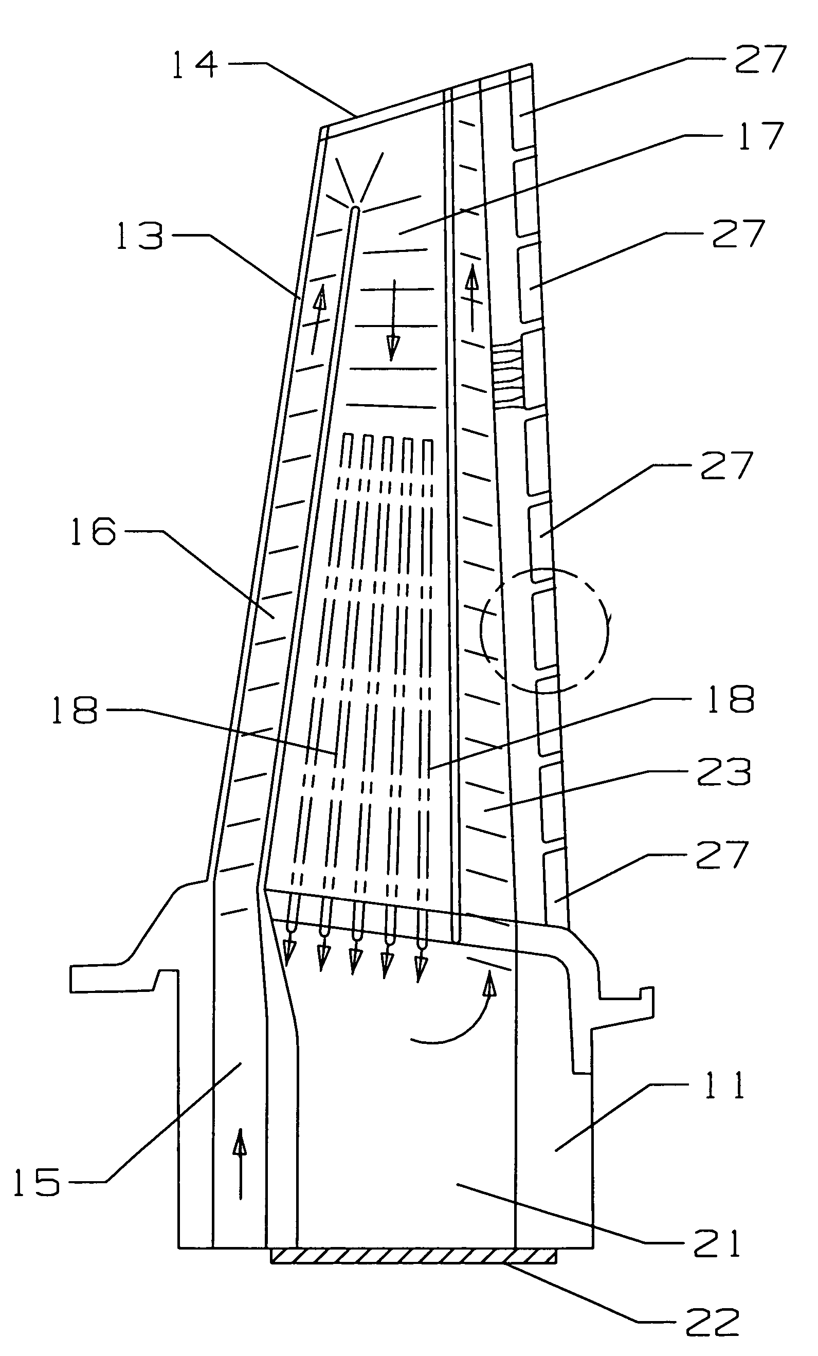
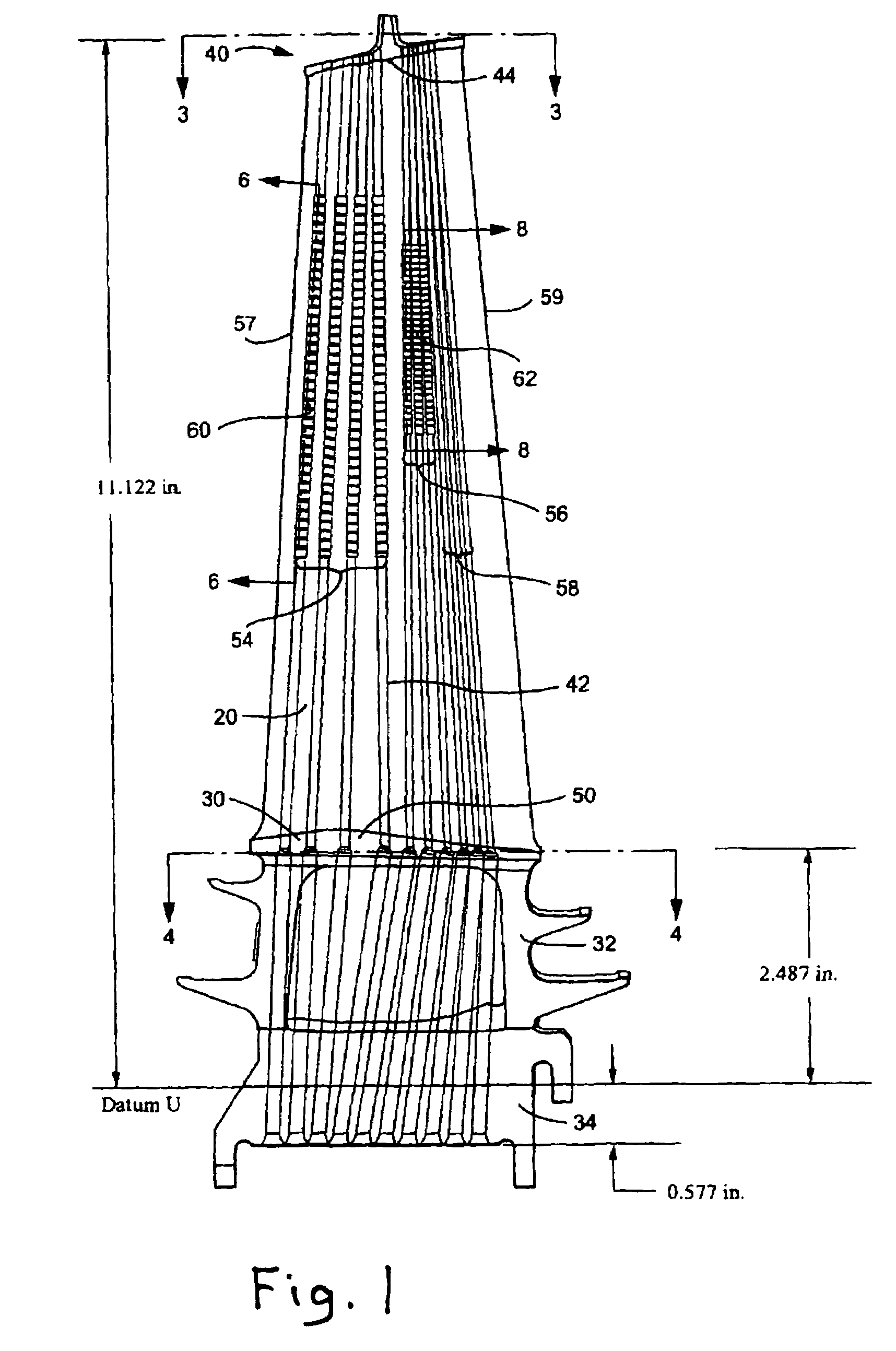
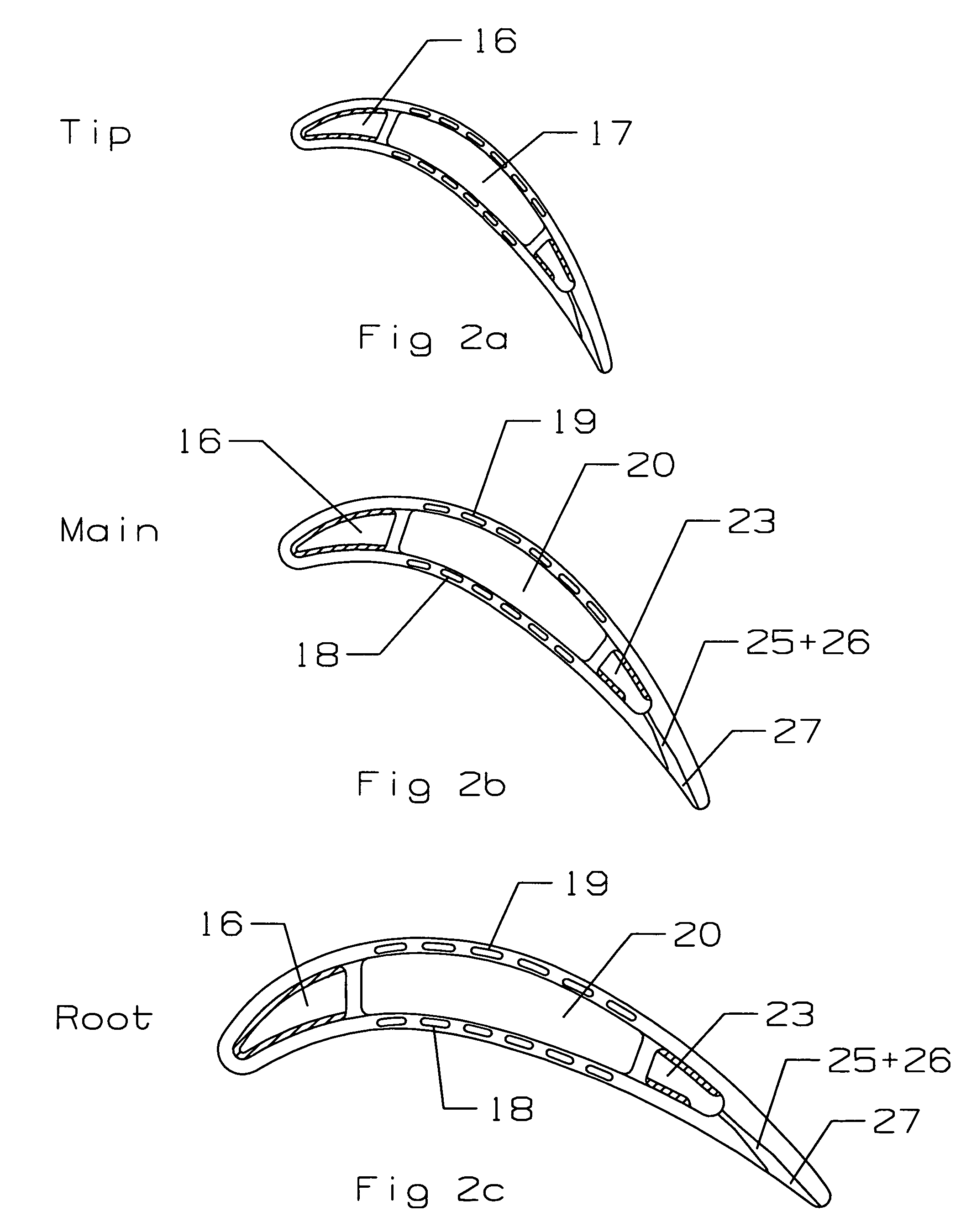
[0025]The present invention is for a large turbine rotor blade used in a gas turbine engine in which the blade includes a large amount of taper and twist that makes it difficult if not impossible to form radial cooling channels from the root to the tip. However, the cooling circuit could be used in not so large rotor blades or stator vanes without departing from the spirit and scope of the invention.

[0026]FIG. 3 is a best representation of the serpentine flow cooling circuit in the turbine blade of the present invention. The blade includes a root portion 11, an airfoil portion 13, and a tip portion 14. A cooling air supply passage 15 is in the root portion 11 and leads into a first leg of the 3-pass serpentine flow cooling circuit. The first leg is a leading edge cooling channel 16 that extends from the root supply channel 15 to the blade tip 14 and turns into the second leg 17 at the tip 14. Trip strips are included within the leading edge channel 16 to promote turbulence within th...


PUM


Abstract

A turbine rotor blade for use in a gas turbine engine, the blade including a serpentine flow cooling circuit that includes a first leg forming a leading edge cooling channel, a second leg that includes an upper channel with trip strips and a lower portion with near wall cooling channels that split off from the upper portion of the second leg to form near wall cooling channels extending along the pressure side and the suction side of the blade, the near wall cooling channels being separated by a dead cavity, and a third leg formed along the trailing edge of the blade with a collecting cavity formed in the blade root and providing the fluid communication between the trailing edge third leg and the near wall cooling channels. The trailing edge channel is connected to a plurality of metering and diffusion holes spaced along the trailing edge. These exit holes include a metering hole, a first diffusion hole, and a diffusion slot located on the pressure side of the trailing edge of the blade. A plurality of the metering and diffusion holes opens into a single diffusion slot. The diffusion slots each include a second diffusion hole and a third diffuser arranged in series.

Description

BACKGROUND OF THE INVENTION[0001]1. Field of the Invention[0002]The present invention relates generally to fluid reaction surfaces, and more specifically to large turbine airfoils with a cooling circuit.[0003]2. Description of the Related Art including information disclosed under 37 CFR 1.97 and 1.98[0004]A gas turbine engine is very efficient machine that converts the chemical energy of a burning fuel into mechanical energy. An industrial gas turbine (IGT) engine is used in power plants to drive an electric generator to produce electric power. The efficiency of a gas turbine engine can be increased by increasing the high temperature gas flow that enters the turbine. It is a very important design feature to provide for the first stage stator vanes and rotor blades to have as high of a high heat resistance as possible by using high temperature resistant materials in combination with internal and film cooling of the airfoils (vanes and blades).[0005]In the recent history of industrial...

Claims


Application Information

Patent Timeline
Patent Type & Authority Patents(United States)
IPC IPC(8): F01D5/18
CPCF01D5/187F05D2240/122F05D2240/304F05D2250/185F05D2260/2214
Inventor LIANG, GEORGE
Owner SIEMENS ENERGY INC
Why Eureka
Try Eureka