Ceilinf fan blade

a fan blade and ceiling fan technology, applied in the field of ceiling fan blades, can solve the problems of blades bursting apart, blades degumming, endanger users, etc., and achieve the effects of avoiding being broken, reducing the risk of damage, and avoiding damage to the blad

Active Publication Date: 2014-07-31
AIR COOL INDAL
View PDF1 Cites 5 Cited by
  • Summary
  • Abstract
  • Description
  • Claims
  • Application Information

AI Technical Summary

Benefits of technology

[0007]The ceiling fan blade of this invention is to have the engage posts respectively engaged with the engage fasteners to form one-way engagement for securing the upper blade on the lower blade, able to reinforce combination of the upper blade with the lower blade. The ceiling fan blade of this invention is not only friendly to the environment but also able to avoid being broken apart when used to insure safety in use. In addition, the ceiling fan blade of this invention is hollow in structure, able to lighten the blade, and there is no locking member on the surface, able to maintain beautiful appearance of the blade.

Problems solved by technology

However, a great quantity of adhesive must be employed for sticking and combining the upper blade and the lower blade of the conventional ceiling fan together and thus, it is not only unfriendly to the environment but also likely to cause degumming to the blades and render the blades burst apart to endanger users when the conventional ceiling fan blades are used.
Although locking members can be used to lock the upper and the lower blades together and reinforce their combination, yet the locking members, after locked, will be exposed to the surface of the blade to spoil the external looks of the conventional ceiling fan.

Method used


Image

  • Ceilinf fan blade
  • Ceilinf fan blade
  • Ceilinf fan blade

Examples


Embodiment Construction

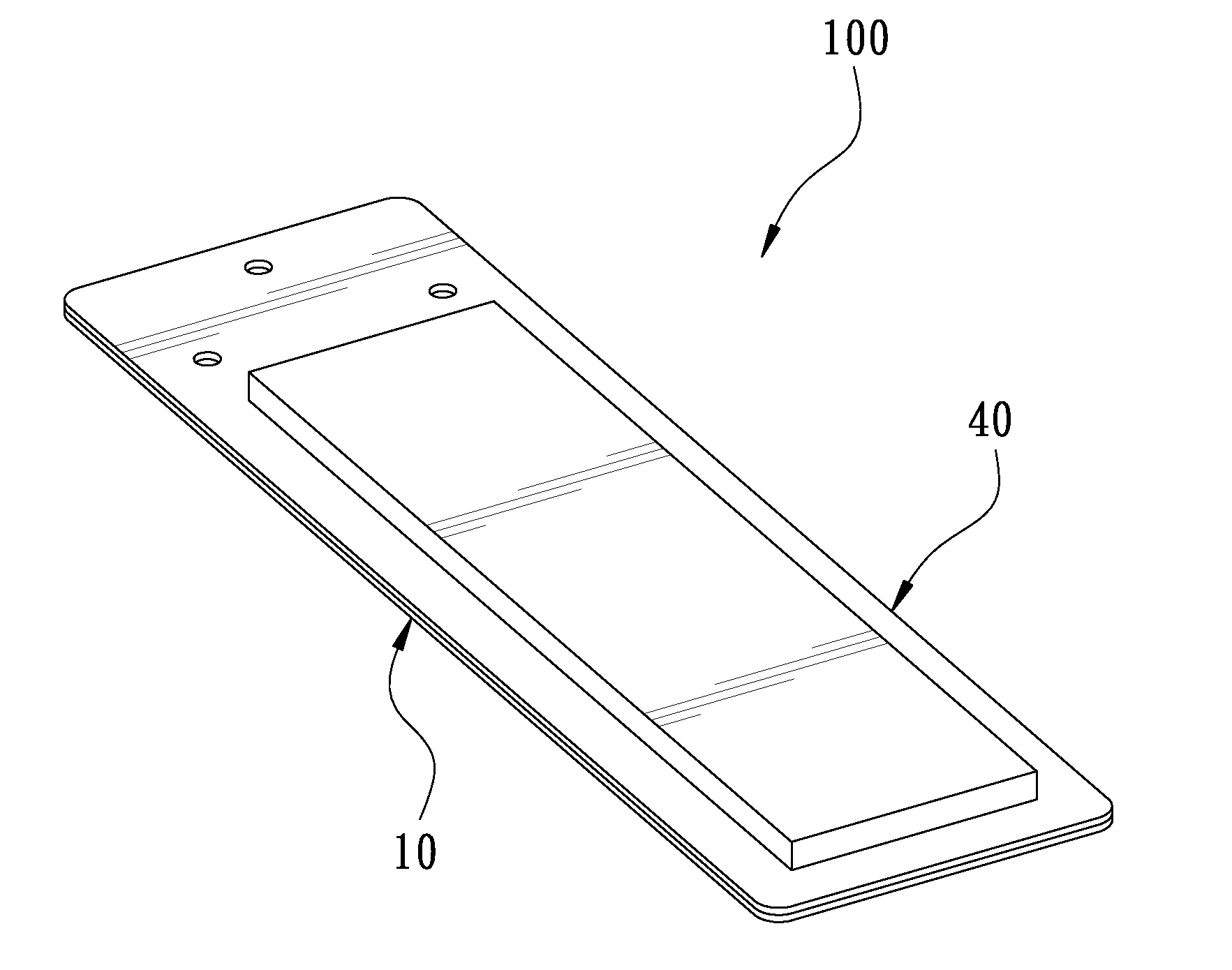
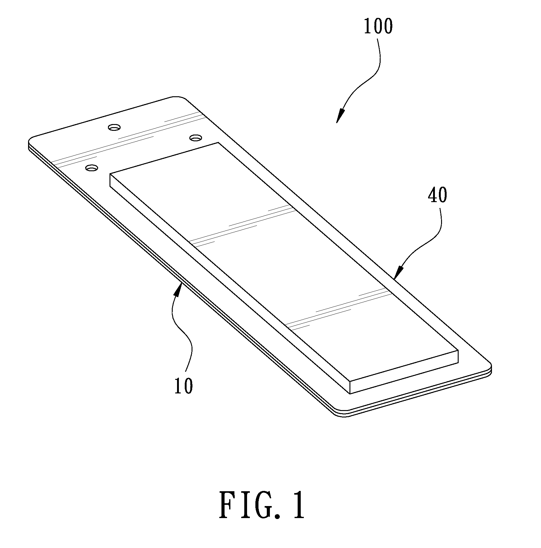
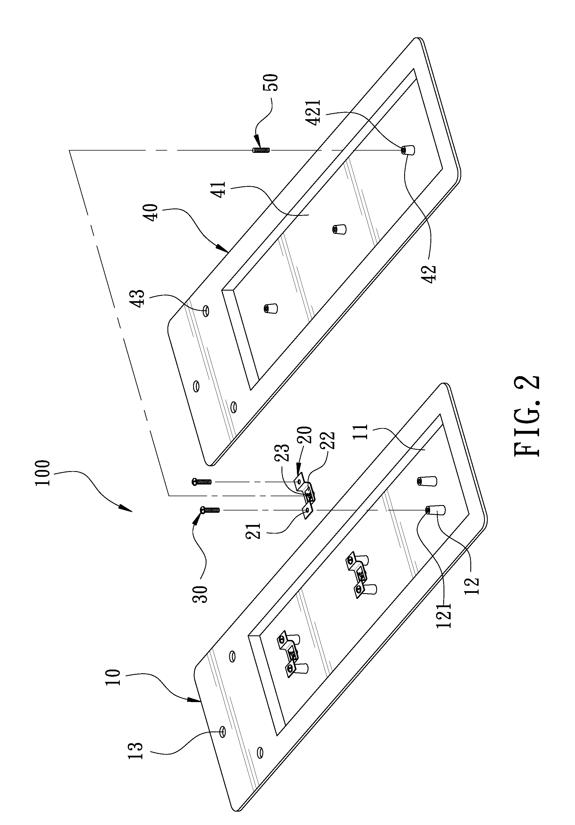
[0015]A preferred embodiment of a ceiling fan blade 100 in the present invention, as shown in FIGS. 1 and 2, includes a lower blade 10, a plurality of engage fasteners 20, a plurality of locking members 30, an upper blade 40 and a plurality of engage posts 50 as main components combined together.

[0016]The lower blade 10 is formed with a recess 11 fixed therein with plural pairs of lower studs 12 spaced apart equidistantly and respectively having a topside disposed with a threaded hole 121. The lower blade 10 further has one end bored with a plurality of through holes 13.

[0017]The engage fasteners 20, referring to FIG. 3, are metal plates formed integral by compression. Each engage fastener 20 has two ends respectively provided with a locking hole 21 to be secured with the lower stud 12 of the lower blade 10, and a central part formed with an engage portion 22 composed of a left engage plate 221 and a right engage plate 222. One end of the left engage plate 221 is a fixed end secured...


PUM


Abstract

A ceiling fan blade includes a lower blade and an upper blade combined together. The lower blade is provided with a recess and secured thereon with a plurality of engage fasteners, and the upper blade is formed with a recess and embedded therein with a plurality of engage posts respectively corresponding with the engage fasteners. The engage post is engaged with the engage fastener to form a one-way engagement for reinforcing combination of the upper blade with the lower blade. The ceiling fan blade of this invention can not only conform to environmental protection but also avoid being broken apart when used to insure safety in use. In addition, the ceiling fan blade of this invention is hollow in structure, able to lighten the blade, and no locking member is provided on the surface of the blade, able to keep beautiful external features of the ceiling fan.

Description

BACKGROUND OF THE INVENTION[0001]1. Field of the Invention This invention relates to a ceiling fan blade.[0002]2. Description of the Prior Art[0003]A common ceiling fan includes a motor having a rotating shaft provided thereon with a plurality of blade holders respectively secured with a blade so that the blades of the ceiling fan can be driven to rotate by the motor and, for facilitating the blades to be driven to rotate by the motor, the common ceiling fan blade is hollow in structure in order to lighten the blade. A conventional ceiling fan blade is generally composed of an upper blade and a lower blade stuck and combined together by means of adhesives and having an accommodating space formed between the upper and the lower blades.[0004]However, a great quantity of adhesive must be employed for sticking and combining the upper blade and the lower blade of the conventional ceiling fan together and thus, it is not only unfriendly to the environment but also likely to cause degummin...

Claims


Application Information

Patent Timeline
Patent Type & Authority Applications(United States)
IPC IPC(8): F01D5/30
CPCF01D5/30F04D25/088F04D29/388
Inventor WANG, CLIFF
Owner AIR COOL INDAL
Why Eureka
Try Eureka