
Waste water treatment method and waste water treatment apparatus

a technology of waste water treatment and waste water treatment, which is applied in the direction of chemistry apparatus and processes, biological water/sewage treatment, sustainable biological treatment, etc., can solve the problems of affecting the ecosystem, affecting the effect of ecosystem health, and difficult to decompose pfos or pfoa in such a conventional treatment as to use microorganisms, photocatalysts or the like, so as to effectively decompose the organic compounds contained in

Active Publication Date: 2010-01-05
SHARP KK
View PDF25 Cites 16 Cited by
  • Summary
  • Abstract
  • Description
  • Claims
  • Application Information

AI Technical Summary

Benefits of technology

The present invention provides a waste water treatment method and apparatus that can effectively decompose organofluoric compounds and organochlorine using microorganisms. The method involves adding micro-nano bubbles to the waste water and then introducing it into a microbe tank for microbial treatment. The micro-nano bubbles activate the microorganisms, resulting in efficient decomposition of the organic compounds. The waste water treatment method can be carried out in two stages, with the second-stage treatment using charcoal adsorption to further enhance the decomposition efficiency. The apparatus includes a micro-nano bubble generation tank, a mixing tank, a microbe tank, and an activated charcoal adsorption device. The technical effects of the invention include effective treatment of waste water containing organofluoric and organochlorine compounds.

Problems solved by technology

However, it is difficult to microbially decomposite the organofluoric compounds or organochlorine compounds because they are chemically stable.
This causes concern about harmful influence on the ecosystem.
On the other hand, however, it is extremely difficult to decompose PFOS or PFOA in such a conventional treatment as to use microorganisms, photocatalysts or the like.
As is stated above, there has not conventionally been known a method for decomposing the organofluoric compounds and the organochlorine compounds, which are chemically stable substances, reasonably at low costs.

Method used


Image

  • Waste water treatment method and waste water treatment apparatus
  • Waste water treatment method and waste water treatment apparatus
  • Waste water treatment method and waste water treatment apparatus

Examples


first embodiment

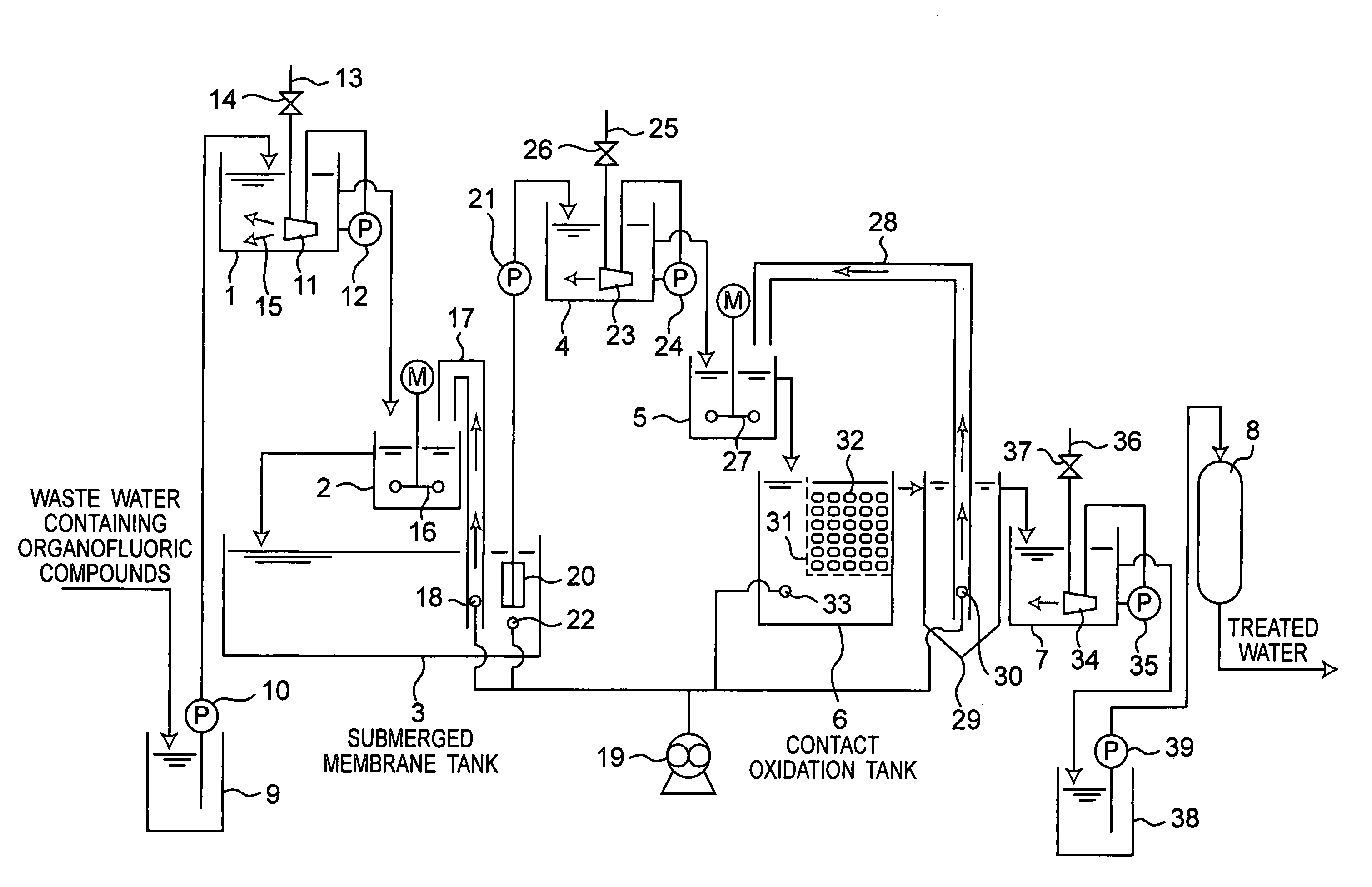
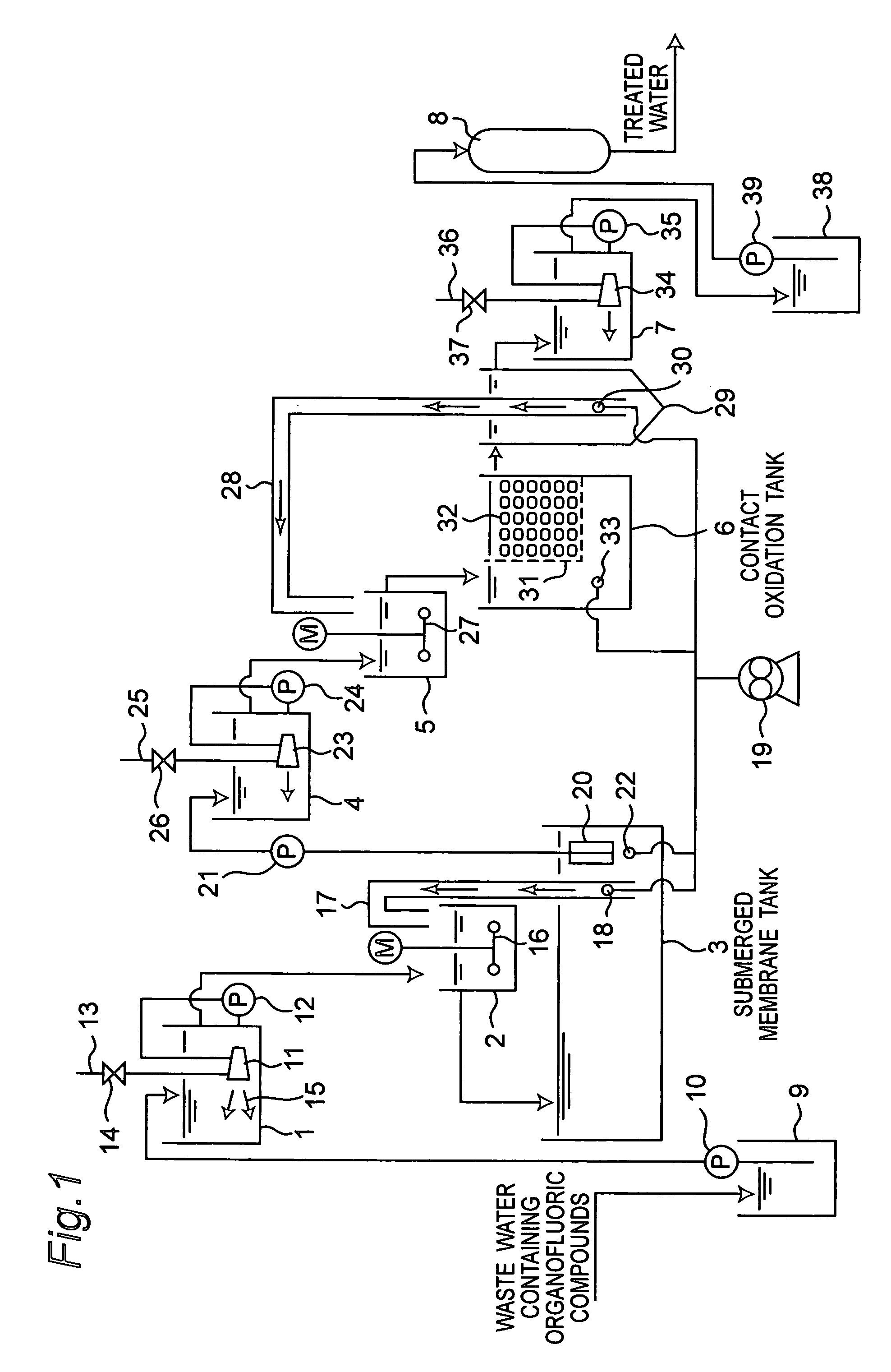
[0069]FIG. 1 is a schematic block diagram showing a waster water treatment apparatus for treating waste water containing organofluoric compounds by a waste water treatment method according to the first embodiment of the present invention.

[0070]In this embodiment, the waste water containing organofluoric compounds are treated mainly in three stages as described below. In a first stage, the waster water is treated in a first micro-nano bubble generation tank 1, a first mixing tank 2, and a submerged membrane tank 3. In a second stage, the waste water is treated in a second micro-nano bubble generation tank 4, a second mixing tank 5 and a contact oxidation tank 6. In a third stage, the waste water is treated in a third micro-nano bubble generation tank 7 and an activated charcoal adsorption device 8.

[0071]Reference numeral 9 in FIG. 1 denotes a raw water tank, to which the waste water containing organofluoric compounds is introduced. The waste water containing organofluoric compounds, ...

second embodiment

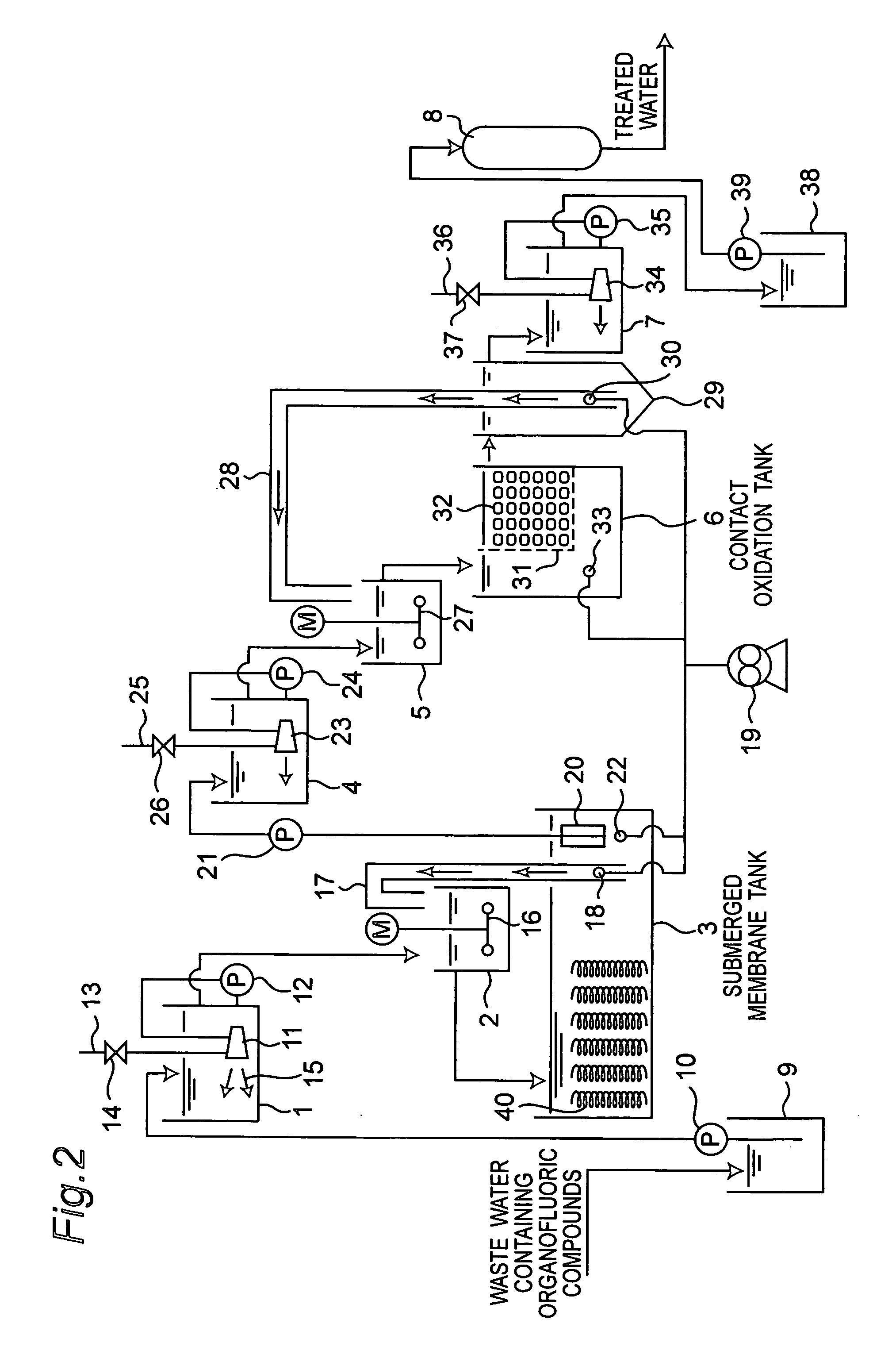
[0092]FIG. 2 is a schematic block diagram showing a waster water treatment apparatus in the second embodiment. In this embodiment, a polyvinylidene chloride filling is provided in the submerged membrane tank 3 shown in FIG. 1 of the first embodiment.

[0093]In FIG. 2, the component members identical to those shown in FIG. 1 for the first embodiment are designated by identical reference numerals. The detailed description thereof will be omitted. Hereinbelow, description will be given of different points from the first embodiment.

[0094]In this embodiment, the polyvinylidene chloride filling 40 is provided in the submerged membrane tank 3 as mentioned just above, and therefore the polyvinylidene chloride filling 40 allows the microorganisms, which are activated by micro-nano bubbles, to stably propagate. This makes it possible to stabilize water quality at the outlet of the submerged membrane tank 3, more specifically, the submerged membrane pump 21.

[0095]Further, since the polyvinyliden...

third embodiment

[0096]FIG. 3 is a schematic block diagram showing a waster water treatment apparatus in the third embodiment. The first mixing tank 2, which is shown in FIG. 1 of the first embodiment, is removed in this embodiment.

[0097]In FIG. 3, the component members identical to those shown in FIG. 1 for the first embodiment are designated by identical reference numerals. The detailed description thereof will be omitted. Hereinbelow, description will be given of different points from the first embodiment.

[0098]In the present embodiment, the first mixing tank 2 of the first embodiment is removed. Therefore, the submerged membrane tank 3 provides a place where the micro-nano bubbles in treatment-receiving-water and the microorganisms in sludge transported by the air lift pump 17 come into contact each other. As a result, performance is slightly degraded in comparison with the first embodiment because of lack in the efficient contact between the micro-nano bubbles and the microorganisms in the firs...


PUM

PropertyMeasurementUnit
diameteraaaaaaaaaa
diameteraaaaaaaaaa
diameteraaaaaaaaaa

Abstract

A waster water treatment apparatus has micro-nano bubbles generation tanks, mixing tanks, a submerged membrane tank, a contact oxidation tank, and an activated charcoal adsorption device. In the micro-nano bubbles generation tanks, micro-nano bubbles are added to the waste water. In the mixing tanks, the waste water containing micro-nano bubbles is mixed with sludge containing microorganisms. In the contact oxidation tank, the waste water containing organofluoric compounds is microbially treated by the micro-nano bubbles added to the waste water. The micro-nano bubbles activate microorganisms in the waste water. Thereby organofluoric compounds are microbially decomposed with effect.

Description

CROSS-REFERENCE TO RELATED APPLICATIONS[0001]This nonprovisional application claims priority under 35 U.S.C. §119(a) on Patent Application No. 2005-281648 filed in Japan on 28 Sep. 2005, the entire contents of which are incorporated herein by reference.BACKGROUND OF THE INVENTION [0002]The present invention relates to waste water treatment method and waste water treatment apparatus.[0003]Organofluoric compounds and organochlorine compounds are chemically stable substances. The organofluoric compounds in particular are used for application such as surface-active agents since they have excellent properties in terms of heat resistance and chemical resistance.[0004]However, it is difficult to microbially decomposite the organofluoric compounds or organochlorine compounds because they are chemically stable. Perfluorooctane sulfonic acid (PFOS) or perfluoro octanoic acid (PFOA), which is an example of the organofluoric compounds, is hardly decomposed in the ecosystem. This causes concern ...

Claims


Application Information

Patent Timeline
Patent Type & Authority Patents(United States)
IPC IPC(8): C02F3/00
CPCC02F3/12C02F3/121C02F3/20C02F3/1273C02F1/283Y02W10/15C02F2101/36Y02W10/10
Inventor YAMASAKI, KAZUYUKISAKATA, KAZUYUKICHUHJOH, KAZUMI
Owner SHARP KK
Learn More