Roller spacing apparatus and image forming device having the same

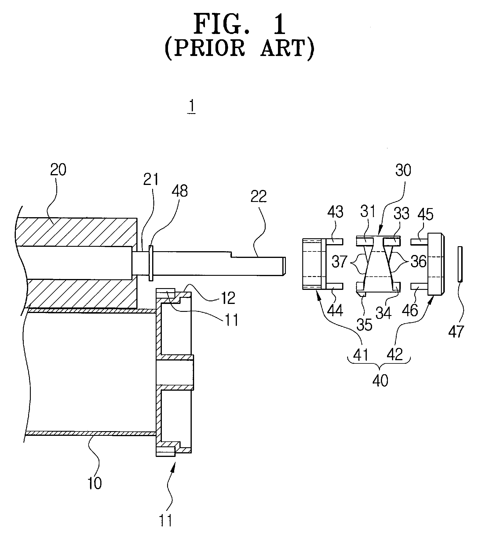
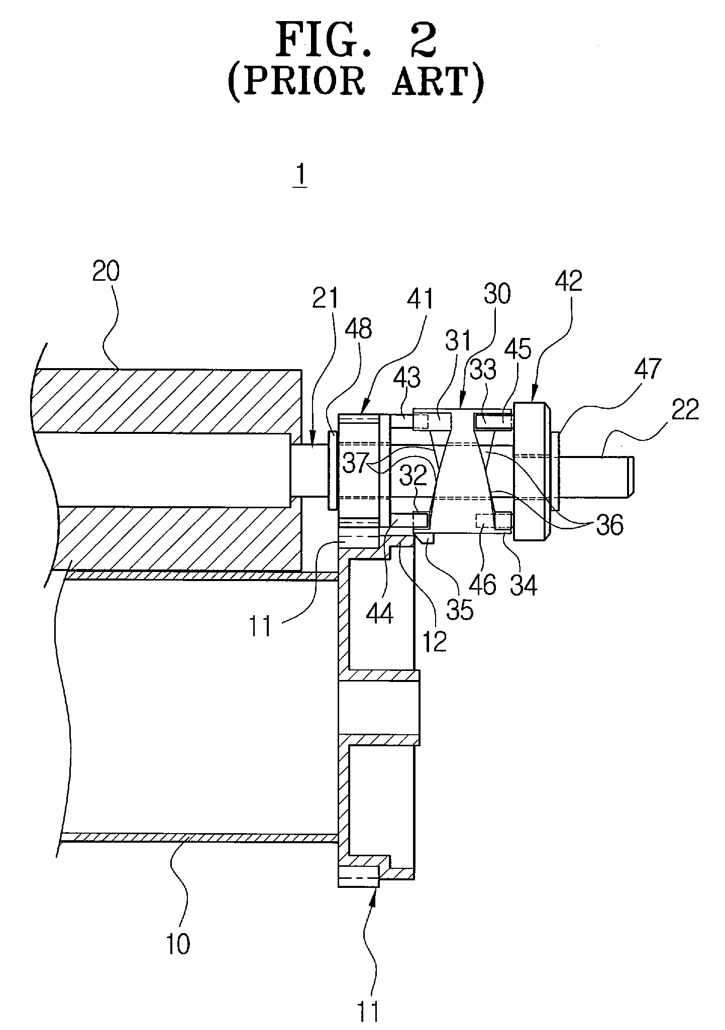
a technology of image forming device and rolling roller, which is applied in the direction of electrographic process apparatus, corona discharge, instruments, etc., can solve the problems of image degradation, physical or chemical damage of the elastic layer of the photoconductive medium, and/or the physical or chemical damage of the developing roller and/or the charging roller

Inactive Publication Date: 2010-01-05
S PRINTING SOLUTION CO LTD
View PDF13 Cites 15 Cited by
  • Summary
  • Abstract
  • Description
  • Claims
  • Application Information

AI Technical Summary

Benefits of technology

[0031]The present general inventive concept provides a roller spacing apparatus that prevents elastic layers of two rollers (e.g., a photoconductive medium and a developing roller, or a photoconductive medium and a charging roller), which rotate in close contact with each other under a predetermined pressure, from being physically and permanently compression set as a result of maintaining the two rollers in a contact state or a partial contact state when the two rollers are not in use, and an image forming device having the same.

Problems solved by technology

In this case, physical and chemical changes may cause device components to malfunction and may cause image degradation.
As a result, a reliability of the device may deteriorate.
Accordingly, there is a problem that the elastic layer of the photoconductive medium, the developing roller, and / or the charging roller may be physically or chemically damaged.

Method used


Image

  • Roller spacing apparatus and image forming device having the same
  • Roller spacing apparatus and image forming device having the same
  • Roller spacing apparatus and image forming device having the same

Examples


Embodiment Construction

[0069]Reference will now be made in detail to the embodiments of the present general inventive concept, examples of which are illustrated in the accompanying drawings, wherein like reference numerals refer to the like elements throughout. The embodiments are described below in order to explain the present general inventive concept by referring to the figures.

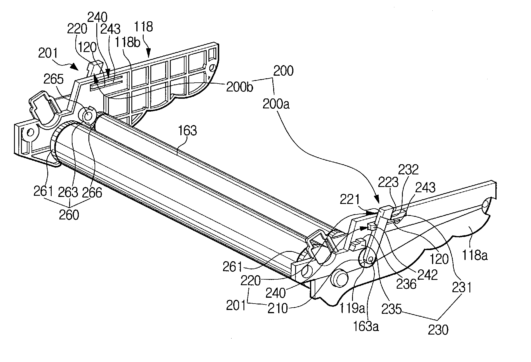
[0070]FIG. 4 is a schematic view illustrating an image forming device 100 according to an embodiment of the present general inventive concept. Although not illustrated in FIG. 4, the image forming device 100 includes a roller spacing unit 200 described below with reference to FIGS. 5 and 6.

[0071]The image forming device 100 may be a laser printer 100 that prints and outputs data input from an external device, such as a computer. However, it should be understood that the present general inventive concept is not limited to the laser printer 100, and other image forming devices can be used with the present general inventive concept...


PUM


Abstract

A roller spacing apparatus and an image forming device including the same. The roller spacing apparatus includes a frame, a first rotatable roller member having a first shaft, a second rotatable roller member having a second shaft and being rotatable in a close contact with the first roller member under a predetermined pressure, and at least one spacing part to space apart the first and the second roller members from each other by a predetermined gap such that the first and the second roller members are not in contact with each other when the first and the second roller members are not in use. The at least one spacing part includes a bushing member that has a bushing to rotatably support one of the first and second shafts on the frame, and a lever positioned at the bushing to rotate the bushing, the bushing having an outer diameter part and an inner diameter part to support the one of the first and second shafts, the inner and outer diameter parts being non-concentric circles such that a center point of the inner diameter part is at a different location from a center point of the outer diameter part, a stopping member disposed on the frame to restrict an operation range of the bushing, and a power transmitting member to selectively transmit an external rotation force to the bushing such that the bushing rotates in a direction.

Description

CROSS-REFERENCE TO RELATED APPLICATIONS[0001]This application claims the benefit under 35 U.S.C. §119 of Korean Patent Application No. 2005-131955, filed on Dec. 28, 2005, in the Korean Intellectual Property Office, the entire content of which is incorporated herein by reference.BACKGROUND OF THE INVENTION[0002]1. Field of the Invention[0003]The present general inventive concept relates to an electrophotographic image forming device, such as a laser printer, a digital photocopier, or a facsimile machine. More particularly, the present general inventive concept relates to a roller spacing apparatus to space apart two rollers (e.g., a photoconductive medium and a developing roller, or a photoconductive medium and a charging roller) that rotate in close contact with each other under a predetermined pressure by a predetermined distance, and to maintain the two rollers in a non-contact state when the two rollers are not in use (e.g., during shipping), and an image forming device having t...

Claims


Application Information

Patent Timeline
Patent Type & Authority Patents(United States)
IPC IPC(8): G03G15/00G03G15/02G03G15/04G03G15/06G03G15/08G03G21/16G03G21/18
CPCG03G15/0813G03G2221/163G03G2221/1657G03G15/02
Inventor CHOI, DONG-HYUK
Owner S PRINTING SOLUTION CO LTD
Why Eureka
Try Eureka