
Device for outputting high and/or low energy X-rays

a high and/or low energy x-ray and x-ray technology, applied in the field of x-ray sources, can solve the problems of poor imaging quality, limited adjustment range of electron beams, and deterioration of imaging quality, and achieve the effects of low cost, simple construction and clear imaging

Active Publication Date: 2010-01-12
TSINGHUA UNIV +1
View PDF23 Cites 17 Cited by
  • Summary
  • Abstract
  • Description
  • Claims
  • Application Information

AI Technical Summary

Benefits of technology

[0005]An object of the present invention is to provide a device for outputting high and / or low energy X-rays, by which the imaging quality is good and the adjustment range of electron beams is large.
[0016]With the above configuration, it is possible to adjust the X-ray energy in a larger range comparing with the prior art, and conduct more clear imaging with low energy reflection X-rays that were generated by electron beams of tens KeVs or hundreds KeVs hitting the target, and then conduct the radiotherapy with X-rays generated by electron beams having the energy level of MeVs. The high and / or low energy X-rays of the present invention can both be pulsed, and can achieve the alternate switching between the high and low energy X-ray pulses. The device according to the present invention has simple construction and low cost, and is adapted to be used in various linear accelerator devices.

Problems solved by technology

However, in this case, the quality of the imaging is poor because it is difficult for the low energy electron beams to be lower than 100 KeV.
In this case, the adjustment range of the electron beams is limited and the imaging quality deteriorates.

Method used


Image

  • Device for outputting high and/or low energy X-rays
  • Device for outputting high and/or low energy X-rays
  • Device for outputting high and/or low energy X-rays

Examples


Embodiment Construction

[0032]It is noted that the following embodiments are used only to explain the present invention, but by no means to limit the scope of the present invention.

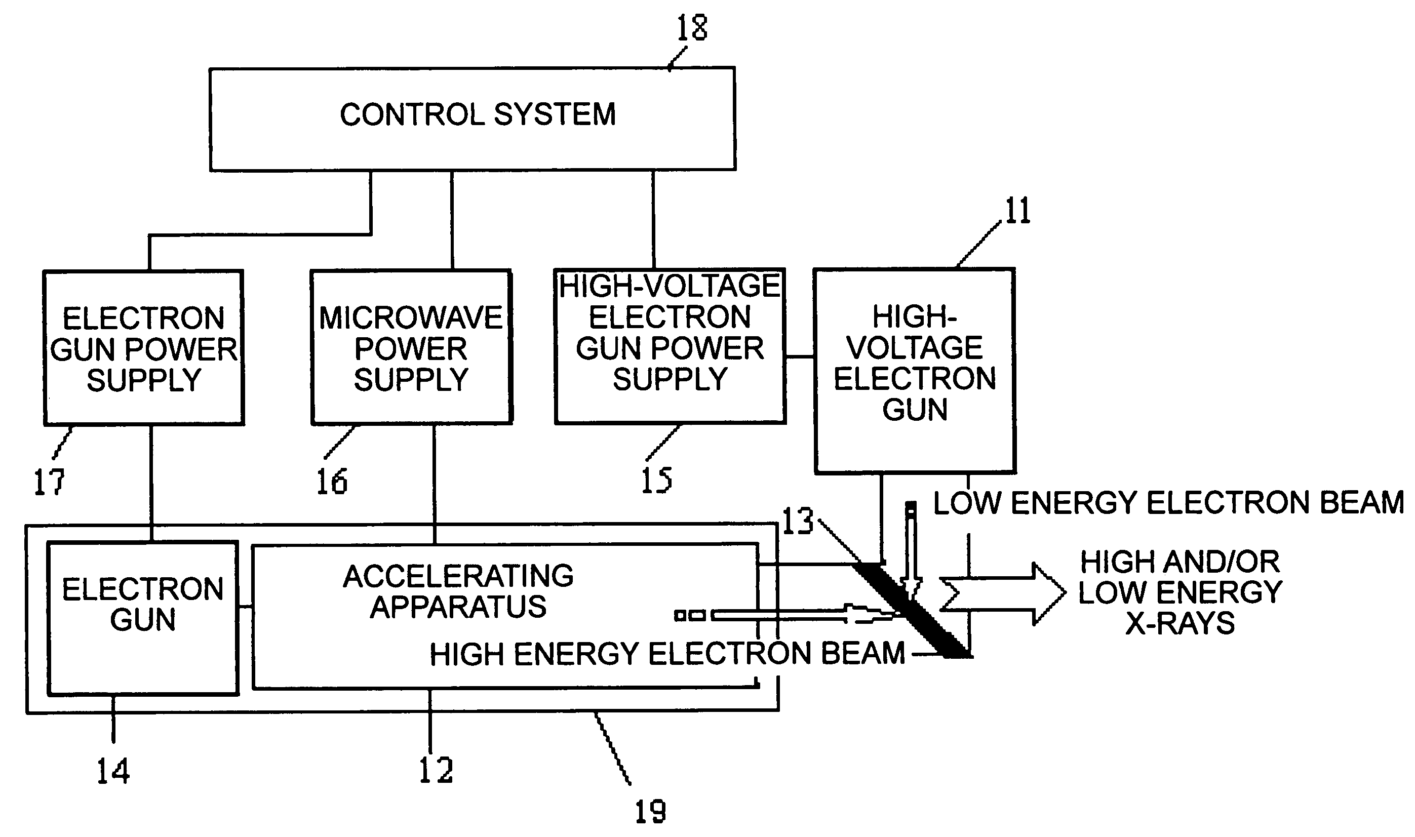
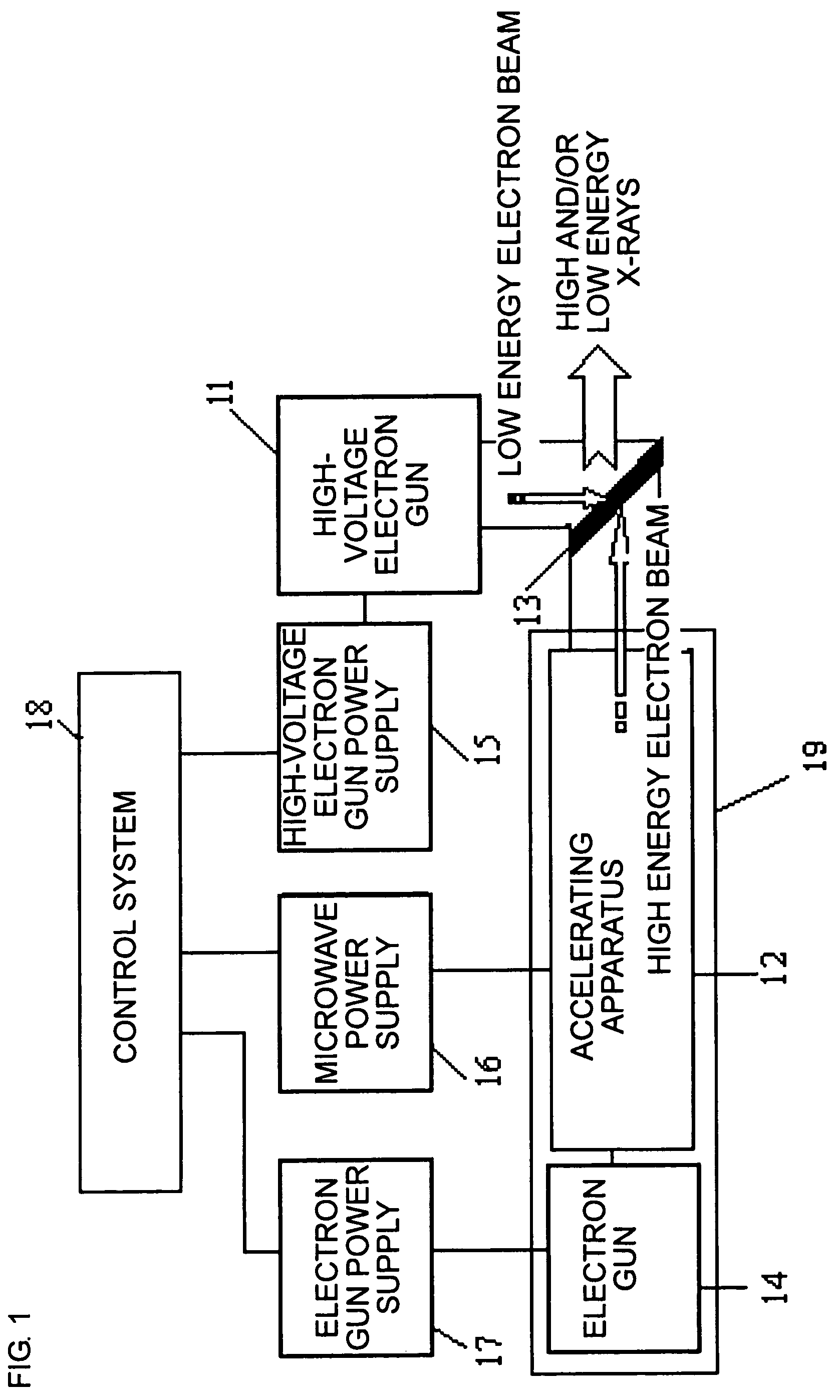
[0033]FIG. 1 is a schematic diagram showing the configuration of a device for outputting high and / or low energy X-rays according to an embodiment of the invention.

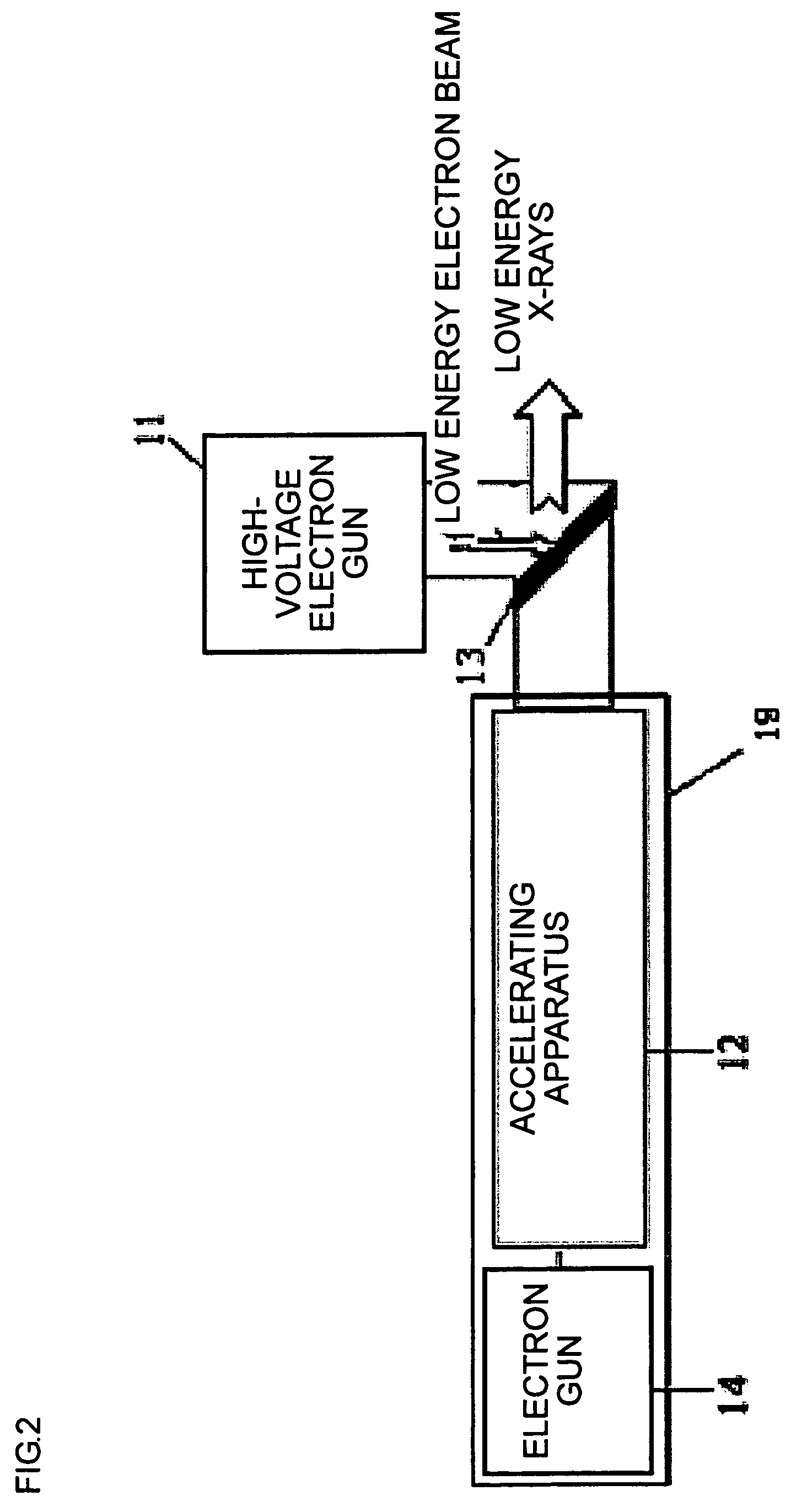
[0034]Referring to FIG. 1, in a device for outputting high and / or low energy X-rays, an electron linear accelerating tube 19 constituted by an electron gun 14 and an accelerating apparatus 12 is a high energy electron beam generating apparatus, and the generated high energy electron beams hit the radiation target 13 disposed downstream of a high-voltage electron gun 11 and the accelerating apparatus 12, so that high energy transmission X-rays are generated at the right side of the radiation target 13. An low energy electron beams generating apparatus is constituted by the high-voltage electron gun 11 and a high-voltage electron gun power supply 15 thereof, and the gene...


PUM


Abstract

Disclosed is a device for outputting high and / or low energy X-rays, in which the electron gun power supply provides power to the electron linear accelerating tube under the control of the control system; the microwave power source accelerates electron beams generated by the electron linear accelerating tube under the control of the control system; the electron linear accelerating tube is connected to the electron gun power supply and the microwave power source respectively, to generate high energy electron beams; the high-voltage electron gun power supply provides power to the high-voltage electron gun under the control of the control system; the high-voltage electron gun is connected to the voltage electron gun power supply to generate low energy electron beams; the radiation target receives the high energy electron beams to generate high energy transmission X-rays, and / or receive the low energy electron beams to generate low energy reflection X-rays. The present invention can be applied in the radiotherapy and the medical imaging, or can be applied in the nondestructive inspection.

Description

[0001]The present application claims priority of Chinese patent application Serial No. 200510135933.2, filed Dec. 31, 2005, the content of which is hereby incorporated by reference in its entirety.FIELD OF THE INVENTION[0002]The present invention relates to an X-ray source, and more particularly, to a device for outputting high and / or low energy X-rays.BACKGROUND OF THE INVENTION[0003]An electron linear accelerator may generate high energy electron beams or thus generate X-rays by having high energy electron beams hit a target. The radiotherapy is a processing technology that makes an irradiated article generate certain biological and physical effects by means of the ionization capability and the Bremsstrahlung effect of electron beams or X-rays, thereby treating tumors. Generally, in the radiotherapy, the focus area of a patient is firstly imaged and located with an analog localizer, and the radiation therapy is conducted with regard to the set therapy area based on the imaging-loc...

Claims


Application Information

Patent Timeline
Patent Type & Authority Patents(United States)
IPC IPC(8): H01L27/146H01J23/34H05H7/00H01J5/18
CPCH05G2/00H01J35/00G21K5/00A61N5/10H01J2235/088
Inventor TANG, CHUANXIANGCHEN, HUAIBILIU, YINONGCHENG, JIANPINGLIU, YAOHONGLI, RENKAI
Owner TSINGHUA UNIV
Learn More