Oscillation control device and synchronization system

a control device and synchronization system technology, applied in the field of oscillator control devices and synchronization systems, can solve the problems of inability to perform calibration or adjustment in real time, inability to secure traceability, drawbacks of conventional oscillators, etc., to increase the convenience of control and operation of the oscillator, and secure the traceability

Active Publication Date: 2010-01-12
NAT INST OF ADVANCED IND SCI & TECH +1
View PDF4 Cites 0 Cited by
  • Summary
  • Abstract
  • Description
  • Claims
  • Application Information

AI Technical Summary

Benefits of technology

[0011]An object of the present invention is to provide a device and a system, both of which enables the frequency of an oscillator remote from the location of the standard oscillator of the Standard Laboratory to synchronize in real time with the frequency of the standard oscillator.
[0030]In particular, as the standard laboratory is the National Metrology Institute, it becomes possible to secure the traceability with the National Standard by obtaining the frequency synchronized in real time with the National Standard. Therefore, it will be possible to increase convenience of the control and operation of the oscillator.

Problems solved by technology

As it usually takes several days to several weeks in order to get the calibration certificate, this system has a drawback in which such calibration or adjustment can not be performed in real time.
However, because there exists a deviation between the frequency obtained from the GPS and the frequency provided by the standard oscillator of the National Metrology Institute and the scale thereof is not measured, the traceability can not be secured.
As mentioned above, a conventional oscillator has a drawback in which it cannot synchronize its own frequency in real time with the frequency of the standard oscillator located at the remote site.

Method used


Image

  • Oscillation control device and synchronization system
  • Oscillation control device and synchronization system
  • Oscillation control device and synchronization system

Examples


Embodiment Construction

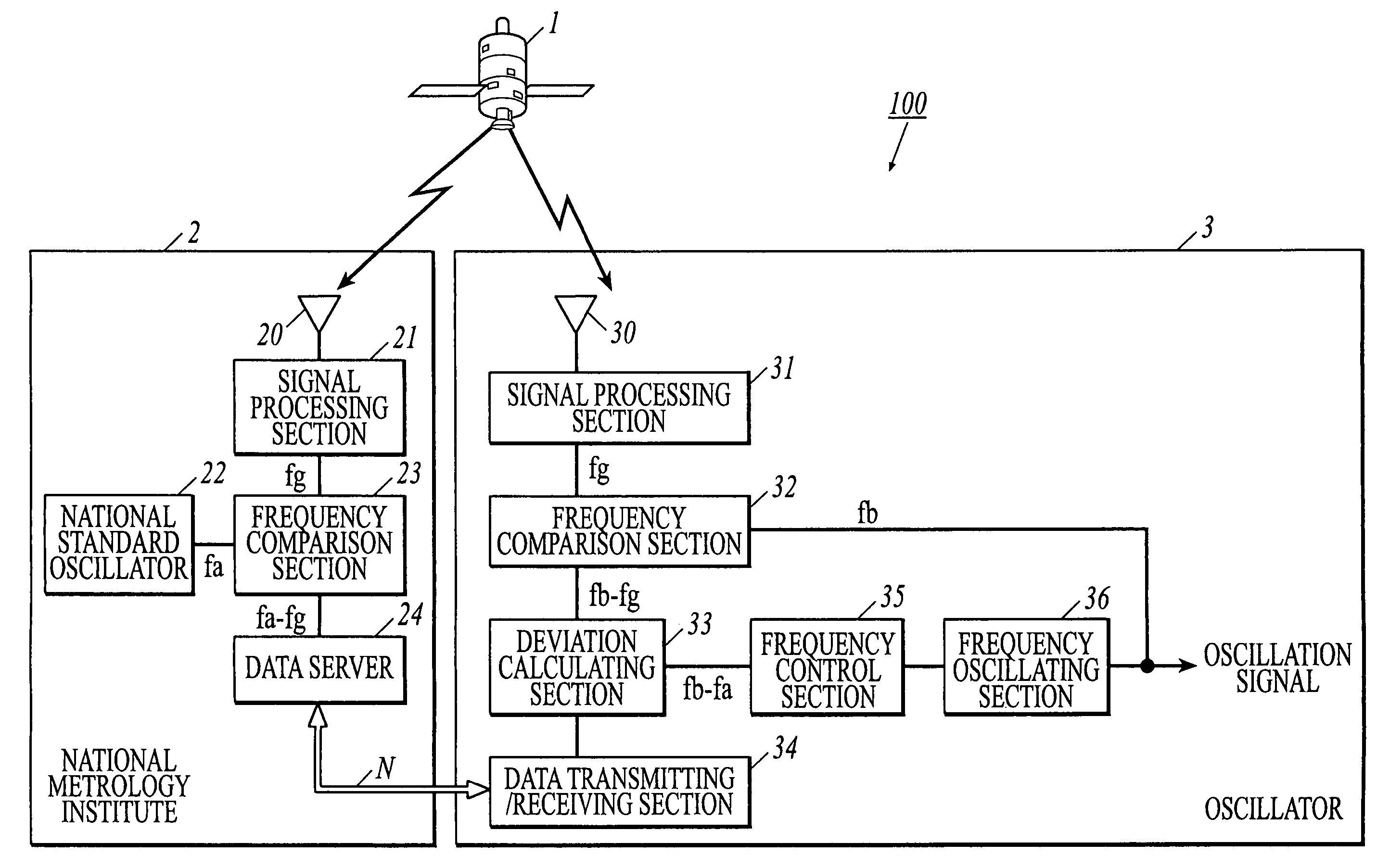
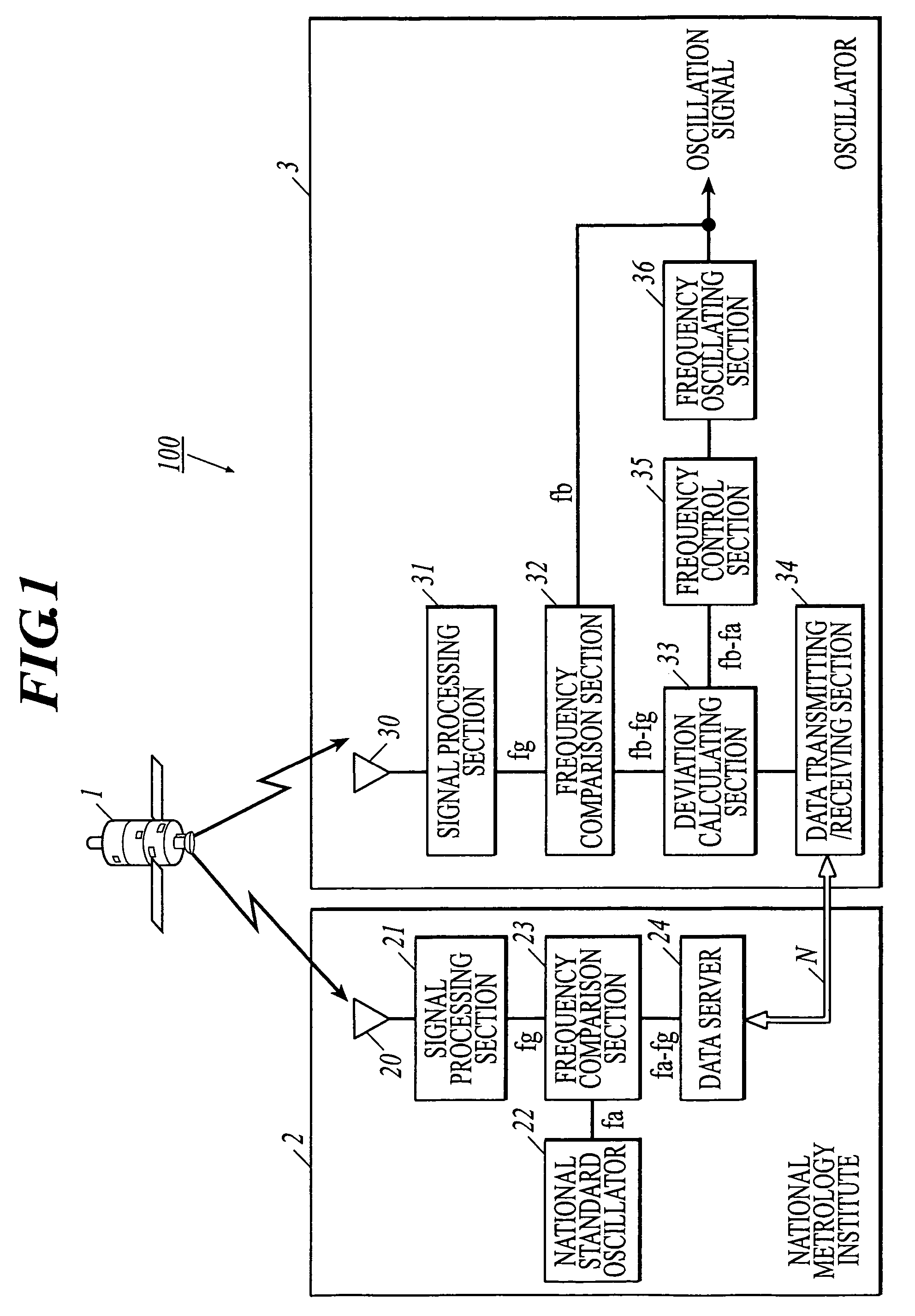
[0035]Referring to the drawings attached herewith, the invention will be described hereinafter in connection with the preferred embodiment. In the explanation of the embodiment, the National Metrology Institute is used as a standard laboratory that holds and operates a high-accuracy standard oscillator and the national standard oscillator is used as a standard oscillator. Hereinafter, a “high-accuracy standard oscillator” means an oscillator which has accuracy as the standard for those oscillators used by other lower standard laboratory or users. Also, for the purpose of explaining the embodiment, the GPS (Global Positioning System) signal transmitted from GPS satellites is used as a “radio signal transmitted from a predetermined point (site) and receivable at a plurality of points (sites)”.

[0036]FIG. 1 shows an arrangement of a synchronizing system 100 according to an embodiment of the invention. As shown in FIG. 1, the synchronization system 100 is comprised of a GPS satellite 1, ...


PUM


Abstract

An oscillation control device for controlling a frequency of an oscillator located at the remote site from a standard laboratory having a standard oscillator. The control device includes: a comparison section to compare a frequency of the frequency signal synchronized with a radio signal produced by a signal processing section with a frequency of a oscillation signal outputted from an oscillator to be controlled, an acquisition section to obtain, through a communication network, a comparison result which is obtained by a comparison of a frequency of the standard oscillator held by the standard laboratory and a frequency of the radio signal, a calculation section to calculate deviation between the frequency of the oscillator to be controlled and the frequency of the standard oscillator based on their comparison, and a control section to control the frequency of the oscillator to be controlled, based on the deviation calculated.

Description

CROSS-REFERENCE TO RELATED APPLICATION[0001]The present U.S. patent application claims a priority under the Paris Convention of Japanese patent application No. 2005-290869 filed on Oct. 4, 2005, and shall be a basis of correction of an incorrect translation.BACKGROUND OF THE INVENTION[0002]1. Field of the Invention[0003]The present invention relates to an oscillation control device for controlling the frequency of an oscillator and to a synchronization system for synchronizing the frequency of the oscillator with the frequency of an oscillator located at a remote site.[0004]2. Description of Related Art[0005]In earlier developments, there is a remote calibration system in which a reference value for enabling the precision measurement for a measurement instrument is supplied from a remote site (See JP-2004-326671A: Document 1). “Calibration” in the remote calibration system means a series of operations for defining the relationship between the value indicated by an instrument or a me...

Claims


Application Information

Patent Timeline
Patent Type & Authority Patents(United States)
IPC IPC(8): H04B1/16H04B1/06G04G3/02
CPCH03L7/00
Inventor IMAE, MICHITOSUZUYAMA, TOMONARIFUJII, YASUHISAKASUMI, YOSHINOBUOGITA, EIJIKAWAKAMI, TOSHIAKI
Owner NAT INST OF ADVANCED IND SCI & TECH
Why Eureka
Try Eureka