Optical-axis deflection type laser interferometer, calibration method thereof, correcting method thereof, and measuring method thereof

Inactive Publication Date: 2008-02-28
MITUTOYO CORP
View PDF4 Cites 11 Cited by
  • Summary
  • Abstract
  • Description
  • Claims
  • Application Information

AI Technical Summary

Benefits of technology

[0012]The present invention has been made to solve the conventional problems. It is therefore an object of the present invention to construct a structure capable of calibrating a displacement gauge used to correct an error in the direction of the optical axis resulting from the motion accuracy of a two-axis rotational mechanism with respect to a reference ball of an optical-axis deflection type laser interferometer, without preparing a special calibrating device, on the operating instrument, thus securing traceability.
[0024]According to the present invention, it is possible to calibrate the displacement gauge used to correct an error in the direction of the optical axis resulting from the motion accuracy of the rotational mechanism with respect to the reference ball of the optical-axis deflection type laser interferometer. A calibrating operation for this can be easily performed in an operating state of the optical-axis deflection type laser interferometer, and a special device is not required to be prepared to calibrate the displacement gauge. As a result, a highly accurate optical-axis deflection type laser interferometer can be realized at low cost.
[0025]Additionally, the calibration of the displacement gauge can be performed by referring only to the measurement value of the laser interferometer length measuring apparatus that is provided in the optical-axis deflection type laser interferometer and that is traceable to the length standard. Therefore, the to-be-calibrated displacement gauge automatically becomes traceable to the length standard, and hence it becomes possible to also perform a calibrating operation that is traceable to the length standard, not only to correct the sensitivity and the nonlinear error of the displacement gauge. Therefore, it is possible to secure traceability by the length standard, which has not easily been achieved by the conventional technique.
[0026]At this time, for example, if a He—Ne wavelength-stabilizing laser having an emission wavelength of 633 nm is employed as a light source, and if the emission wavelength (emission frequency) thereof is calibrated by the comparative measurement with a wavelength-stabilizing laser by an iodine absorption line that is an upper standard, the calibration of the displacement gauge that is traceable to the length standard can be automatically achieved. Additionally, this makes it possible to secure traceability as the whole of the optical-axis deflection type laser interferometer system with ease and at low cost.

Problems solved by technology

However, the optical-axis deflection type laser interferometer has technical difficulties in making the precision of the two-axis rotational mechanism 30 as high as the precision in measurement of the laser interferometer.
These make it difficult to achieve high precision.
However, the optical system disclosed by Patent Document 1 has a disorder of an interference wavefront or a reduction in light quantity with respect to a rotational error (i.e., runout) in a direction perpendicular to the optical axis.
Additionally, it has become apparent that the optical system is not necessarily robust in respect of a change in the optical path length.
Therefore, high-cost specifications are required for the rotational accuracy of the two-axis rotational mechanism 30.
Therefore, if there is a great difference in light quantity between the reference beam of light and the measurement beam of light, the contrast of interference fringes cannot be sufficiently secured, and, as a result, interference measurement cannot be performed with high accuracy.
The light quantity of the measurement beam that has returned in this way is remarkably attenuated, and hence a difference in light quantity with respect to the reference beam that is generally regarded as not being easily attenuated causes a large problem.

Method used


Image

  • Optical-axis deflection type laser interferometer, calibration method thereof, correcting method thereof, and measuring method thereof
  • Optical-axis deflection type laser interferometer, calibration method thereof, correcting method thereof, and measuring method thereof
  • Optical-axis deflection type laser interferometer, calibration method thereof, correcting method thereof, and measuring method thereof

Examples


Embodiment Construction

[0034]An embodiment of the present invention will be hereinafter described in detail with reference to the accompanying drawings.

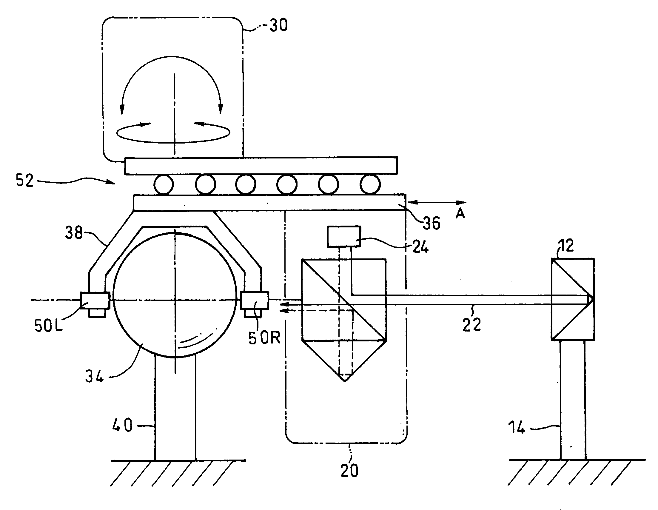
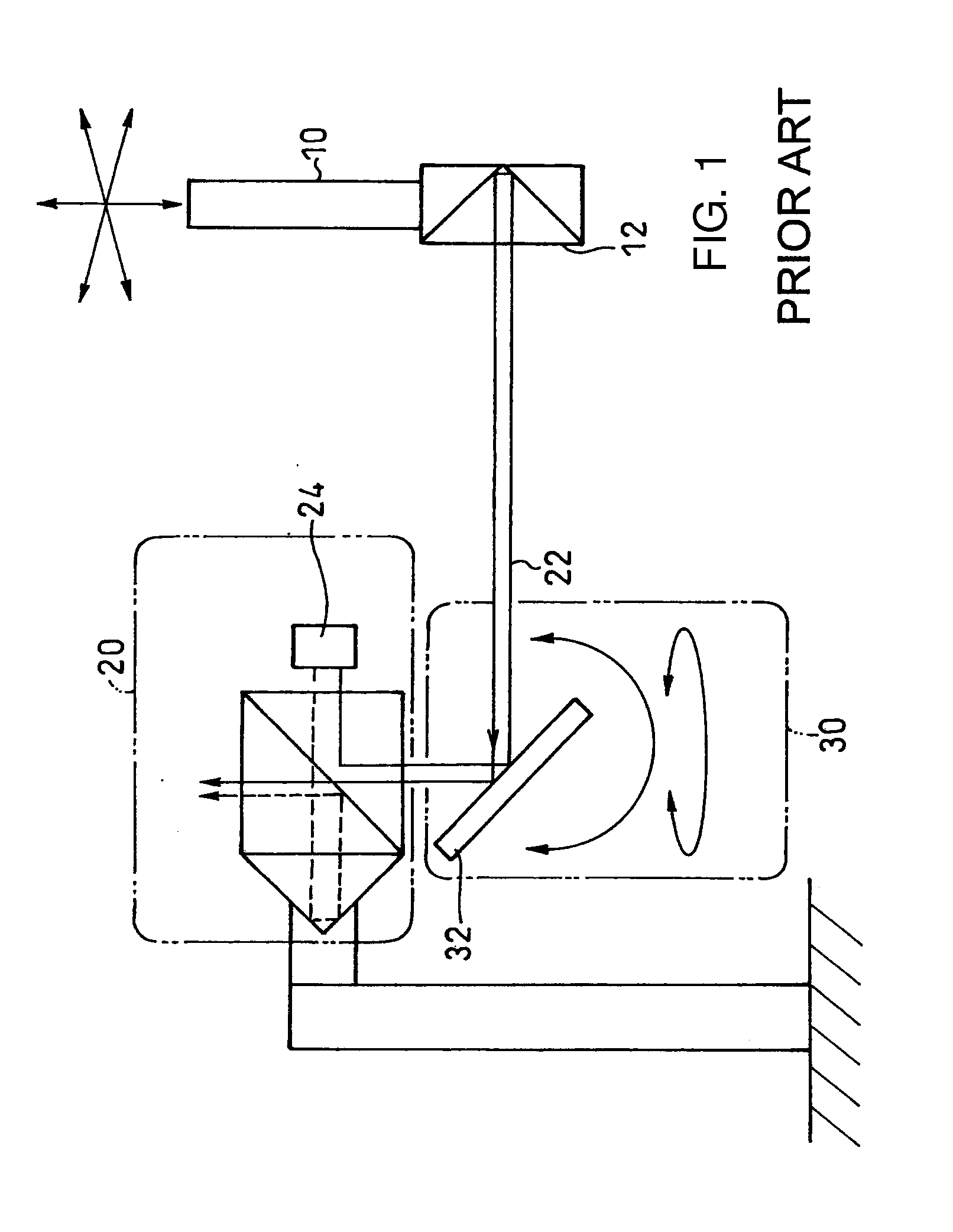
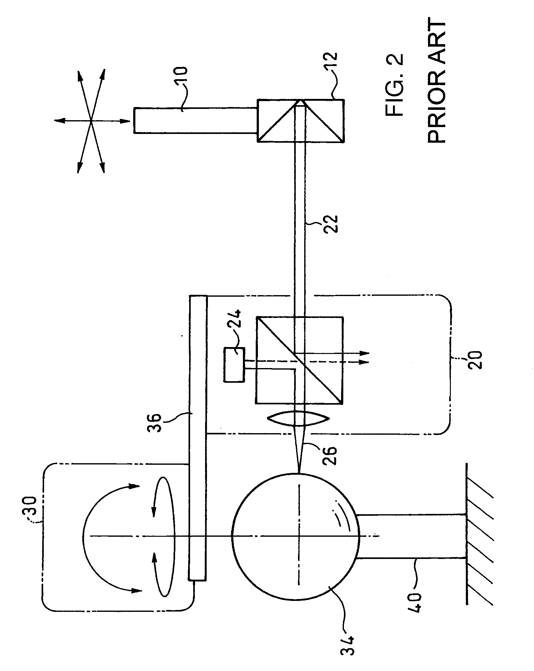
[0035]In this embodiment, a rectilinear movement mechanism 52 that enables a movement in the direction of a measurement optical axis (i.e., in the direction indicated by arrow “A”) is provided between a two-axis rotational mechanism 30 and carriages 36 and 38 that are mechanical components formed integrally with a laser interferometer length measuring apparatus 20 and with displacement gauges 50R and 50L as shown in FIG. 4, in addition to the prior invention that has been proposed by the present applicant in Patent Document 2 as shown in FIG. 3. A movement in the direction of the measurement optical axis by the rectilinear movement mechanism 52 is performed together with the laser interferometer length measuring apparatus 20 and the displacement gauges 50R and 50L.

[0036]Therefore, once the displacement gauges 50R and 50L are calibrated, the system of FIG. ...


PUM


Abstract

An optical-axis deflection type laser interferometer includes a reference ball serving as a measurement reference, a retroreflecting means disposed at an object to be measured, a laser interferometer length measuring apparatus that outputs a measurement value according to an increase or a decrease in distance between the apparatus and the retroreflecting means, and a rotational mechanism that rotates a beam projected from the laser interferometer length measuring apparatus around the reference ball. The thus structured laser interferometer measures a distance between the laser interferometer and the retroreflecting means that makes an optical axis of an outgoing beam projected from the laser interferometer length measuring apparatus mounted on the rotational mechanism and an optical axis of a return beam returned to the laser interferometer length measuring apparatus parallel to each other, based on center coordinates of the reference ball. The laser interferometer is characterized by additionally including a displacement gauge that measures an error caused by a relative motion between the reference ball and the laser interferometer length measuring apparatus, and a rectilinear movement mechanism that displaces these in a direction of an optical axis of a measurement beam with respect to the reference ball while maintaining a relative positional relationship between the laser interferometer length measuring apparatus and the displacement gauge. With this structure, it becomes possible to calibrate the displacement gauge used to correct an error in the direction of the optical axis resulting from the motion accuracy of the two-axis rotational mechanism with respect to the reference ball of the optical-axis deflection type laser interferometer, without preparing a special calibrating device, on the operating instrument. As a result, traceability is secured.

Description

CROSS-REFERENCE TO RELATED APPLICATION[0001]The disclosure of Japanese Patent Application No. 2006-229164 filed on Aug. 25, 2006 including specifications, drawings and claims is incorporated herein by reference in its entirety.BACKGROUND OF THE INVENTION[0002]1. Field of the Invention[0003]The present invention relates to an optical-axis deflection type laser interferometer that includes a reference ball serving as a measurement reference, a retroreflecting means disposed at an object to be measured, a laser interferometer length measuring apparatus that outputs a measurement value according to an increase or a decrease in distance between the apparatus and the retroreflecting means, and a rotational mechanism that rotates a beam projected from the laser interferometer length measuring apparatus around the reference ball, the laser interferometer measuring a distance between the laser interferometer and the retroreflecting means that makes an optical axis of an outgoing beam project...

Claims


Application Information

Patent Timeline
IPC IPC(8): G01C3/08
CPCG01S7/497G01B9/02072G01B2290/15G01B9/02049
Inventor UESHIMA, YASUSHITAKETOMI, NAOYUKIABBE, MAKOTO
Owner MITUTOYO CORP
Why Eureka
Try Eureka