Eureka AIR delivers breakthrough ideas for toughest innovation challenges, trusted by R&D personnel around the world.

UV resistant multilayered cellular confinement system

a cellular confinement system and polymer technology, applied in rock-fill dams, instruments, transportation and packaging, etc., can solve the problems of reducing flexibility, impact and puncture resistance, poor tear resistance, and damage to the plastic walls of the ccss, and achieves high durability against uv

Inactive Publication Date: 2010-01-19
GEOTECH TECHNOLOGIES LTD
View PDF12 Cites 11 Cited by
  • Summary
  • Abstract
  • Description
  • Claims
  • Application Information

AI Technical Summary

Benefits of technology

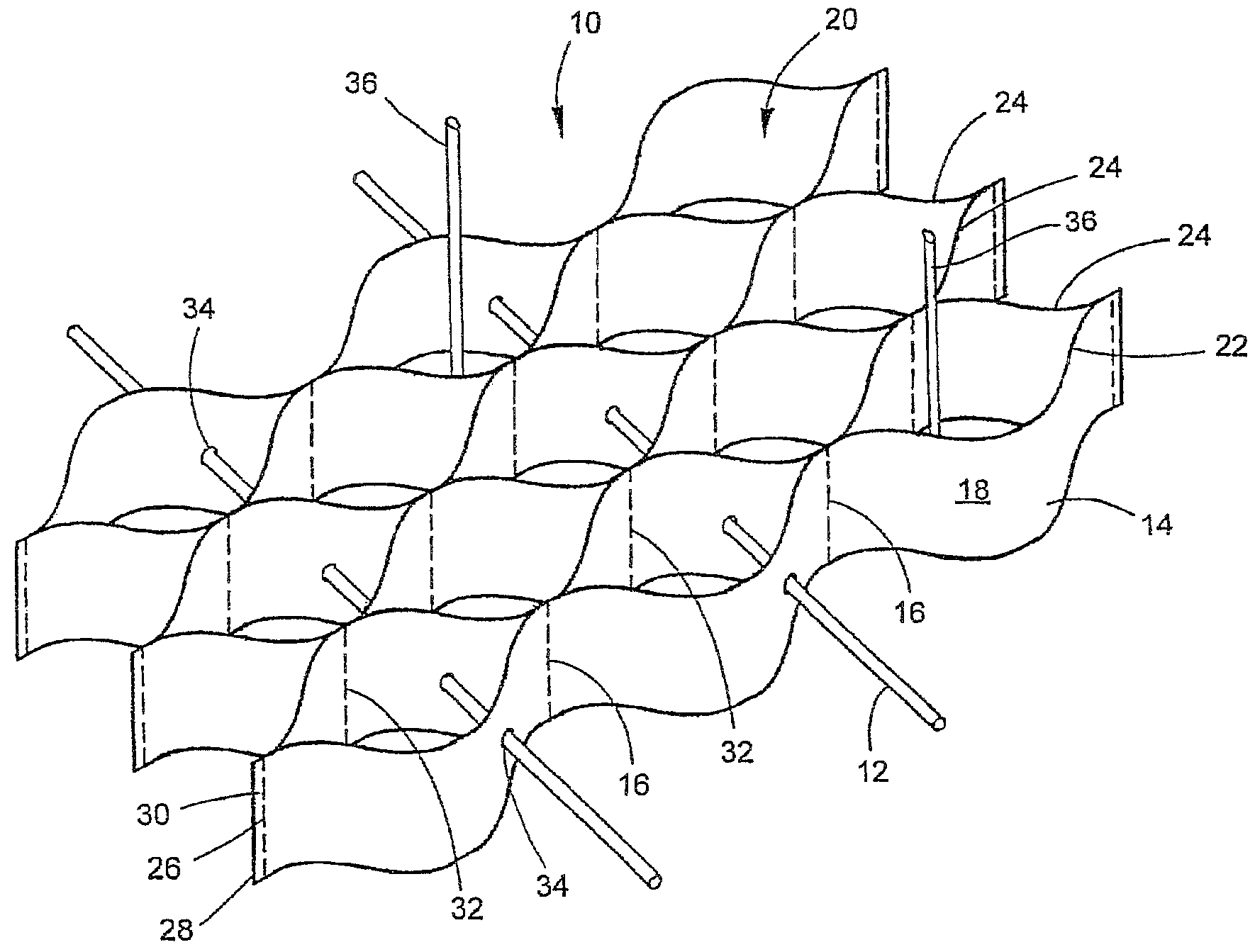
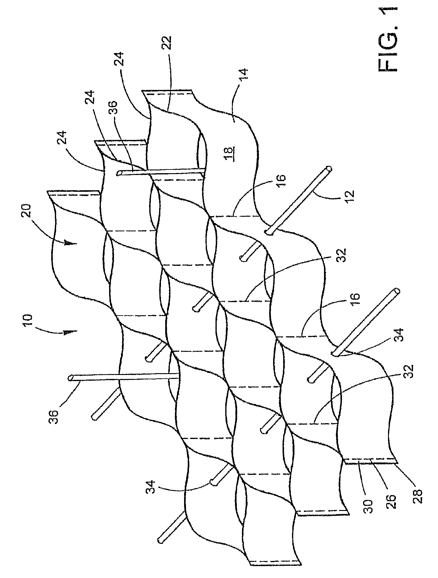
[0022]The present disclosure is directed to a geotechnical article, especially a cellular confinement system (CCS), which exhibits high durability against UV light, heat, and humidity, for periods of at least 2 years. In specific embodiments, the CCS exhibits such durability for at least 10 years. In further specific embodiments, the CCS exhibits such durability for at least 20 years and up to 100 years. By durability is meant lack of chalking or cracking, and retention of original color, surface integrity, strength, modulus, elongation to break, puncture resistance, creep resistance, and weld strength.
[0023]In an exemplary embodiment, the CCS comprises a plurality of polymeric strips. Each polymeric strip comprises at least one inner polymeric layer and at least one outer polymeric layer. The at least one outer polymeric layer is more resistant to UV light, humidity, or heat (UHH), than the at least one inner polymeric layer. Each polymeric layer comprises at least one kind of polymer. The at least one outer polymeric layer further comprises a UV absorber or a hindered amine light stabilizer (HALS). The UV absorber blocks and prevents the harmful UV light from penetrating to the at least one inner polymeric layer. The HALS deactivates harmful radicals generated in the outer layer(s) from diffusion into the inner layer(s) of the polymeric strip.

Problems solved by technology

The plastic walls of the CCSs may become damaged during service and use in the field by UV light, heat, and humidity (UHH).
The damage results in brittleness, decreased flexibility, toughness, impact and puncture resistance, poor tear resistance, and discoloration.
In particular, heat damage to the CCS is significant in hot areas on the globe.
However, one disadvantage produced through the use of carbon black is its aesthetic appearance.
Black CCSs are less attractive in applications where the CCS is part of a landscape structure.
A second disadvantage is that black CCSs tend to absorb sunlight and heat up.
HDPE and MDPE tend to creep when heated above 40-50° C. As a consequence, creep can be severely accelerated, especially in the welding points and thinner wall structures, potentially resulting in structural failures.
Without UHH protection, these anchor points may fail before any significant damage is observed in the rest of the CCS.
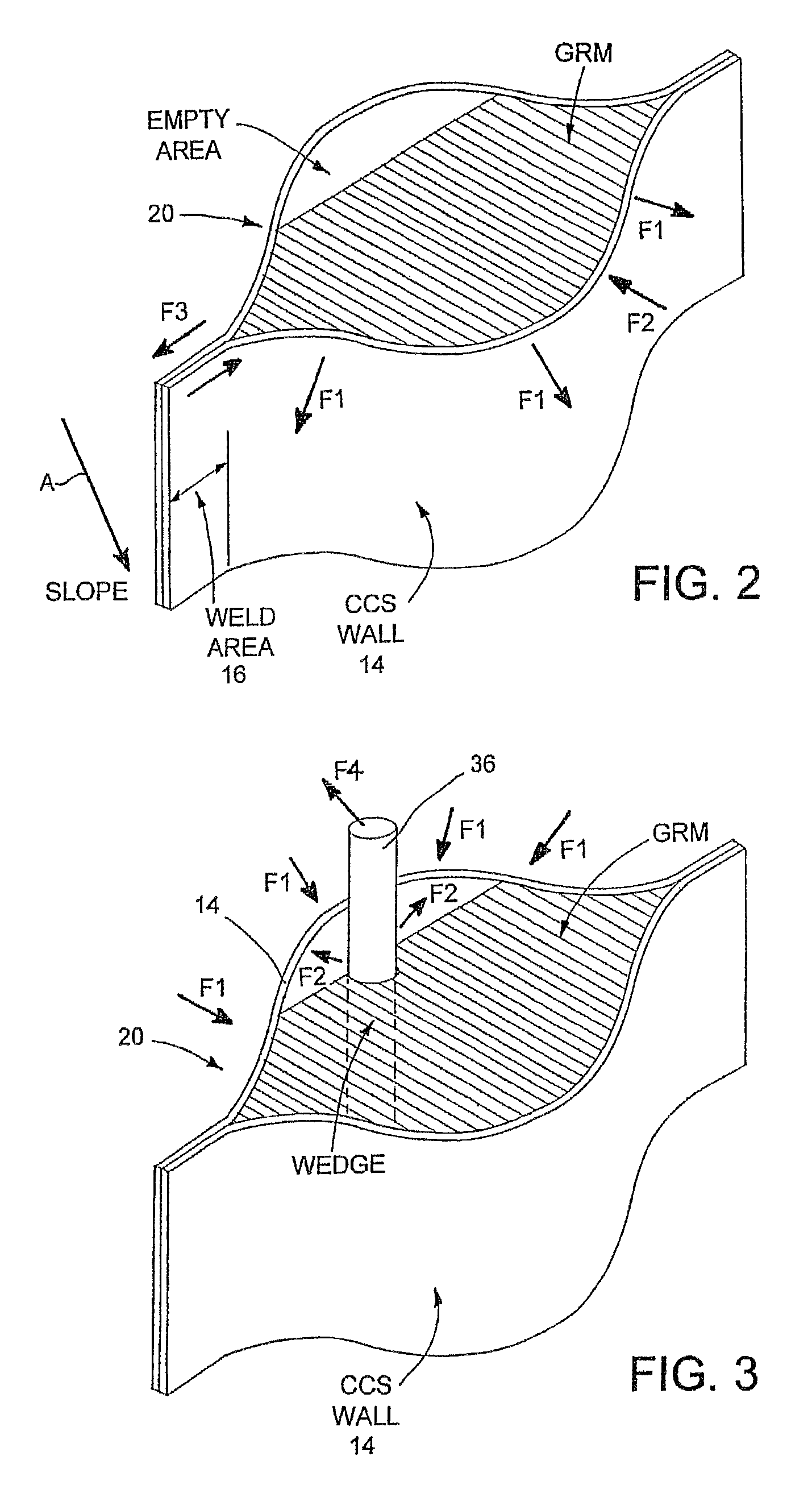
Thus, the HDPE will expand much more than the GRM; this causes stress along the CCS walls and especially at the welds.
Some hot areas, especially tropical areas, also experience high humidity and heavy rains.
Once such additives are lost, the polymeric strip is easily attacked and its properties deteriorate rapidly.
The patent relates to polypropylene and very low density polyethylene compositions that are effective as membranes, but are not practical for CCSs.
Polypropylene is too brittle at sub-zero temperatures.
Very low density polyethylene is too weak for use in a CCS because it tends to creep under moderate loads.
Once a CCS creeps, the integrity of the CCS and GRM is disrupted and structural performance is irreversibly damaged.
In addition, polypropylene requires a large loading of additives to overcome leaching and hydrolysis; this results in an uneconomical polymer.
Polyesters are generally unsuitable for CCSs due to their stiffness, poor impact and puncture resistance at ambient and especially at sub-zero temperatures, medium to poor hydrolytic resistance (especially when in direct contact with basic media such as concrete and calcined soils), and their overall cost.
Again, polyesters require a large loading of additives to overcome leaching and hydrolysis; this results in an uneconomical polymer.
UHH-protecting additives are very expensive relative to the cost of the polymer.
Moreover, HDPE and MDPE provide poor barrier properties against ingress of harmful ions and molecules into the polymer, and against leaching and evaporation of the additives from the polymer.
Because of this, in reality, most manufacturers do not currently guarantee long-term durability of their thick polymeric strips.
Selection of the correct polymer for this application is a tradeoff between economy, i.e. cost of raw materials, and long-term durability.
However, without additives, polyethylene is susceptible to degradation within one year to a degree that is unacceptable for commercial use.
Even when heavily stabilized, PE is still inferior relatively to more UV-resistant polymers, such as ethylene-acrylic ester copolymers and terpolymers.
However, their relatively high cost and relatively low modulus and strength characteristics limit their wide-scale use in CCS applications.

Method used


Image

  • UV resistant multilayered cellular confinement system
  • UV resistant multilayered cellular confinement system
  • UV resistant multilayered cellular confinement system

Examples


example 1

[0087]Five UHH-resistant mixtures, INV1-INV5, and a reference mixture were made. Their composition is shown in TABLE 1. In addition, each mixture comprised 0.5% TiO2 pigment (Kronos™ 2222 manufactured by Kronos) and 0.2% PV Fast Brown HFR™ brown pigment (manufactured by Clariant). The polymers, additives and pigments were fed to a main hopper of a co-rotating twin screw extruder running at 100-400 RPM at barrel temperature of 180 to 240 Celsius. The polymers were melted and the additives were dispersed by at least one kneading zone. Filler was provided from a side feeder. Steam and gases were removed by an atmospheric vent and the product was pelletized by a strand pelletizer.

[0088]

TABLE 1Composition of PolymersIngredientReference1INV1INV2INV3INV4INV5HDPE (Kg)100100100505050LLDPE (Kg)00005050Ethylene-Acrylate0005000(Kg)Talc (Kg)02020202020Organic UV absorber0.150.50.50.50.50.5(Kg)Inorganic UV absorber001111(Kg)HALS (Kg)0.150.50.50.50.50.5Nano-clay (Kg)000001HDPE resin—HDPE M 5010 ma...

example 2

[0093]Five mixtures, INV6-INV10, and a reference mixture were made. Their composition is shown in TABLE 4. In addition, each mixture comprised 0.5% TiO2 pigment (Kronos™ 2222 manufactured by Kronos) and 0.2% PV Fast Brown HFR™ brown pigment (manufactured by Clariant). The polymers, additives and pigments were fed to a main hopper of a co-rotating twin screw extruder running at 100-400 RPM at barrel temperature of 260 to 285 Celsius. The polymers were melted and the additives were dispersed by at least one kneading zone. Filler was provided from a side feeder. Steam and gases were removed by an atmospheric vent and the product was pelletized by a strand pelletizer.

[0094]

TABLE 4Composition of PolymersIngredientReference2INV6INV7INV8INV9INV10MA Functionalized HDPE (kg)0100100704040Virgin HDPE (Kg)10000000LLDPE (Kg)0000300Ethylene-Acrylate (Kg)0000030Recycled PET (Kg)02525252525Talc (Kg)0200202020Organic UV absorber (Kg)0.150.350.150.150.150.15Inorganic UV absorber (Kg)001111HALS (Kg)0....


PUM

PropertyMeasurementUnit
diameteraaaaaaaaaa
particle sizeaaaaaaaaaa
lengthaaaaaaaaaa

Abstract

The present disclosure generally relates to a polymeric cellular confinement system which can be filled with soil, concrete, aggregate, earth materials, and the like. More specifically, the present disclosure concerns a cellular confinement system characterized by improved durability against damage generated by UV light, humidity, and aggressive soils, or combinations thereof.

Description

CROSS-REFERENCE TO RELATED APPLICATIONS[0001]This application is related to U.S. patent application Ser. No. 11 / 680,979, filed concurrently and entitled “GEOTECHNICAL ARTICLES”; and to U.S. patent application Ser. No. 11 / 680,987, filed concurrently and entitled “HIGH PERFORMANCE GEOSYNTHETIC ARTICLE”; to U.S. Provisional Patent Application Ser. No. 12 / 204,088, filed concurrently and entitled “WELDING PROCESS AND GEOSYNTHETIC PRODUCTS THEREOF”; and to U.S. Provisional Patent Application Ser. No. 12 / 040,488, filed concurrently and entitled “PROCESS FOR PRODUCING COMPATIBILIZED POLYMER BLENDS”. All four of these patent applications are hereby incorporated by reference in their entirety.BACKGROUND[0002]The present disclosure generally relates to a polymeric cellular confinement system which can be filled with soil, concrete, aggregate, earth materials, and the like. More specifically, the present disclosure concerns a cellular confinement system characterized by improved durability agai...

Claims


Application Information

Patent Timeline
Patent Type & Authority Patents(United States)
IPC IPC(8): B32B1/00B32B3/12C08F8/00C08L23/00C08L23/04E02B7/02E02B7/08E02B7/14
CPCE02D17/20Y10T428/24661Y10T428/24322Y10T428/24165Y10T428/24157Y10T428/24149Y10T428/24355Y10T428/25Y10T428/24612Y10T428/31565Y10T428/31855Y10T428/31797Y10T428/31736Y10T428/249986Y10T428/249953
Inventor HALAHMI, IZHAREREZ, ODEDEREZ, ADI
Owner GEOTECH TECHNOLOGIES LTD
Why Eureka
Eureka Blog
Learn More