
Heat exchanger

Inactive Publication Date: 2010-01-26
BEHR GMBH & CO KG
View PDF32 Cites 2 Cited by
  • Summary
  • Abstract
  • Description
  • Claims
  • Application Information

AI Technical Summary

Benefits of technology

[0006]The main idea of the invention is to make the surfaces of the subblocks dependent on the size of installation-space-related zones having different air temperatures and to cause coolant to flow first through the subblock within an installation-space-related zone having a higher air temperature, the subblock being arranged preferably within the zone having the highest air temperature.

Problems solved by technology

A corresponding arrangement prevents heat transmission losses, but still leaves much to be desired.
A duplex heat exchanger of this type which consists of two blocks entails a multiplicity of individual parts and a relatively high outlay in production terms, so that production is costly.
Furthermore, a heat exchanger of this type still leaves much to be desired with regard to thermal properties.
Even a radiator of this type, however, still leaves much to be desired in terms of coolant efficiency.

Method used


Image

  • Heat exchanger
  • Heat exchanger
  • Heat exchanger

Examples


Embodiment Construction

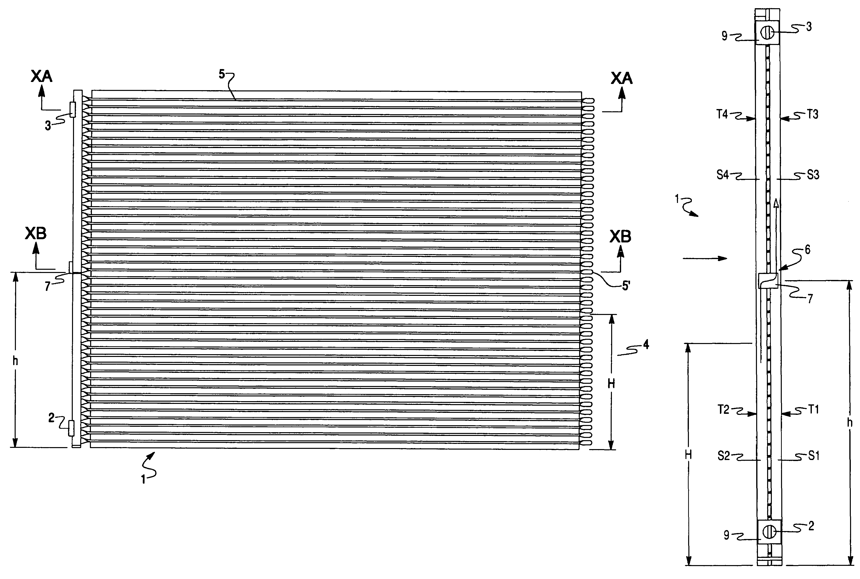
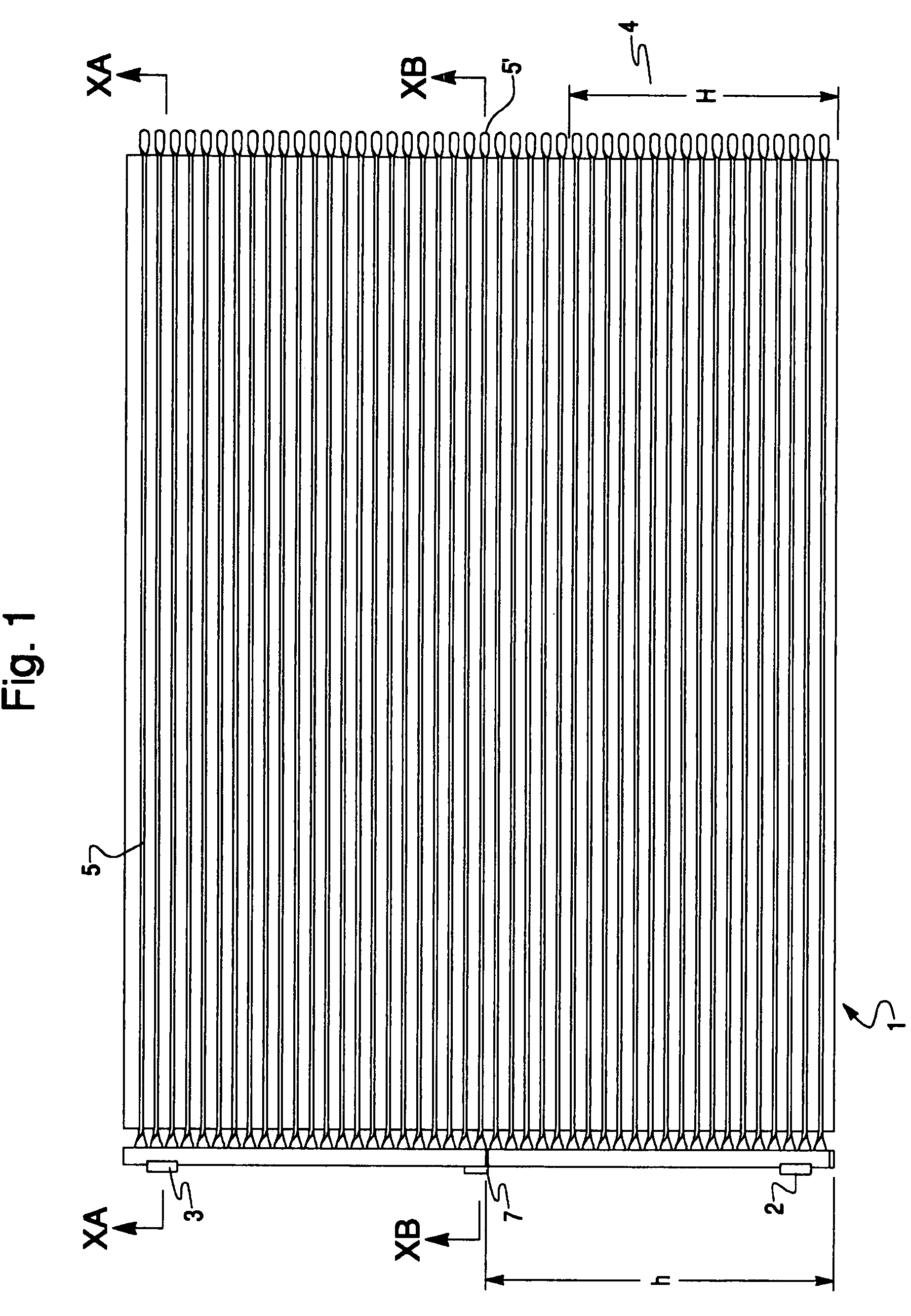
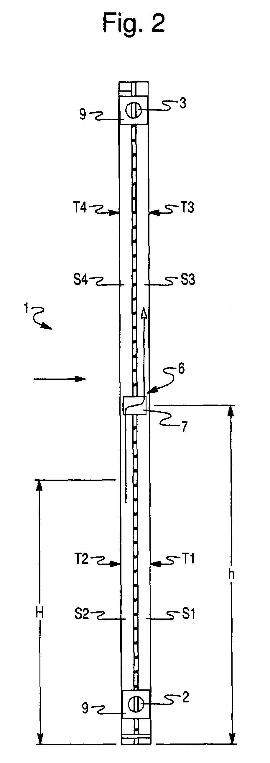
[0034]FIGS. 1 and 2 show a flat-tube heat exchanger for a heating or air-conditioning system of a motor vehicle, which serves as a radiator 1 and is part of a coolant circuit, not illustrated, and which serves for cooling a coolant, in particular CO2, with the aid of the air flowing through the radiator 1. FIG. 2 illustrates the airstream symbolically by an arrow pointing to the radiator 1 from the left. The CO2 is normally in a supercritical state as a pure gas flow, temperatures of around 150° C. prevailing at the inlet 2 into the radiator 1. A cooling of the coolant takes place in the radiator 1, so that temperatures of around 50° C. prevail at the outlet 3.

[0035]In order to allow an optimum utilization of the air flowing through the radiator 1, the radiator 1 is subdivided into 2×2 subblocks which are designated hereafter as T1, T2, T3 and T4. In this case, in the installed state, the subblocks T1 and T2 are arranged within a zone 4 having a higher air temperature and below the ...


PUM


Abstract

The invention relates to a heat exchanger, particularly a radiator for a heating or air conditioning unit in motor vehicles, which cools a coolant. Said heat exchanger (1) is penetrated by air, comprises collector pipes (S1, S2, S2, S4) and several essentially horizontally disposed pipes (5), and is divided into several partial blocks (T1, T2, T3, T4). The surfaces of the inventive partial blocks are selected according to the dimensions of structural space-related zones having different air temperatures inside the assembly space of the heat exchanger, the partial block which is first penetrated by the coolant being arranged within a structural space-related zone having a higher air temperature, preferably within the zone having the highest air temperature.

Description

BACKGROUND OF THE INVENTION[0001]The invention relates to a heat exchanger, in particular a heat exchanger for a heating or air-conditioning system for motor vehicles in which a gaseous refrigerant is cooled by heat exchange contact with ambient air.[0002]EP 0 845 648 A2 discloses a flat-tube heat exchanger, in particular a condenser of the serpentine type, with a flat-tube block consisting of one or more flat tubes which issue with preferably twisted end portions on the opposite or on the same tube block side into respective connection-space components, that is to say header tubes, so that, should the header tubes be arranged on the same tube block side, two header tubes running adjacently and parallel to one another are provided. In this case, a plurality of serpentine-shaped flat tubes may be provided, in which adjacent flat tubes are arranged with their inlet-side or their outlet-side tube portions adjacent to one another in the longitudinal direction of the header tubes, the se...

Claims


Application Information

Patent Timeline
IPC IPC(8): F28F9/26F28F9/02F28D1/047F28F27/02
CPCF28D1/0476F28F9/028F28F9/0246F28F9/0204
Inventor DEMUTH, WALTERKOTSCH, MARTINSTAFFA, KARL-HEINZWALTER, CHRISTOPH
Owner BEHR GMBH & CO KG
Learn More