Antenna, and radio-frequency identification tag

a radio-frequency identification and antenna technology, applied in the direction of antennas, antenna details, electrically short antennas, etc., can solve the problems of reducing the size of the radio-frequency identification tag, increasing the degree, and the risk of deterioration of the antenna characteristics such as its sensitivity value and communication distance, so as to achieve good impedance match, high communication sensitivity, and minimal deterioration of communication characteristics

Inactive Publication Date: 2010-01-26
BROTHER KOGYO KK +1
View PDF23 Cites 13 Cited by
  • Summary
  • Abstract
  • Description
  • Claims
  • Application Information

AI Technical Summary

Benefits of technology

[0010]The antenna according to the first aspect of this invention described above includes the driven meander line portion and the parasitic meander line portion which is positioned relative to the driven meander line portion, so as to influence the input impedance of the driven meander line portion, so that the input impedance of the driven meander line portion can be made close to the input impedance of the circuit portion, by suitably positioning the driven and parasitic meander line portions. Accordingly, a device provided with the antenna can be small-sized, with a minimum matching loss of the input impedance of the driven meander line portion with that of the circuit portion, and with minimum deterioration of communication characteristics of the antenna such as communication sensitivity and maximum communication distance. That is, the first aspect of the invention provides a small-sized antenna which has a good impedance match with a circuit portion and which maintains desired communication characteristics.
[0033]In the radio-frequency identification tag according to the second aspect of the invention, each of the driven meander line portion and the parasitic meander line portion preferably has a conductive path length which is at least ½ of a wavelength of an electromagnetic wave used for the radio communication with the radio-frequency tag communication device. In this case, the radio-frequency identification tag provided with the driven and parasitic meander line portions can be small-sized while maintaining desired communication characteristics such as high communication sensitivity and sufficient maximum communication distance.

Problems solved by technology

However, the size reduction of the radio-frequency identification tag has a problem specific to its construction.
Namely, the size reduction of the radio-frequency identification tag results in reduction of an input impedance of its antenna, and an increase of a degree of mismatch between the input impedance of the antenna and an input impedance of an IC circuit portion connected to the antenna, so that there is a risk of deterioration of the characteristics of the antenna such as its sensitivity value and communication distance.

Method used


Image

  • Antenna, and radio-frequency identification tag
  • Antenna, and radio-frequency identification tag
  • Antenna, and radio-frequency identification tag

Examples


first embodiment

[0114]There will be described other embodiments of this invention. In the following embodiments, the same reference signs as used in the first embodiment will be used to identify the same elements, which will not be described redundantly.

second embodiment

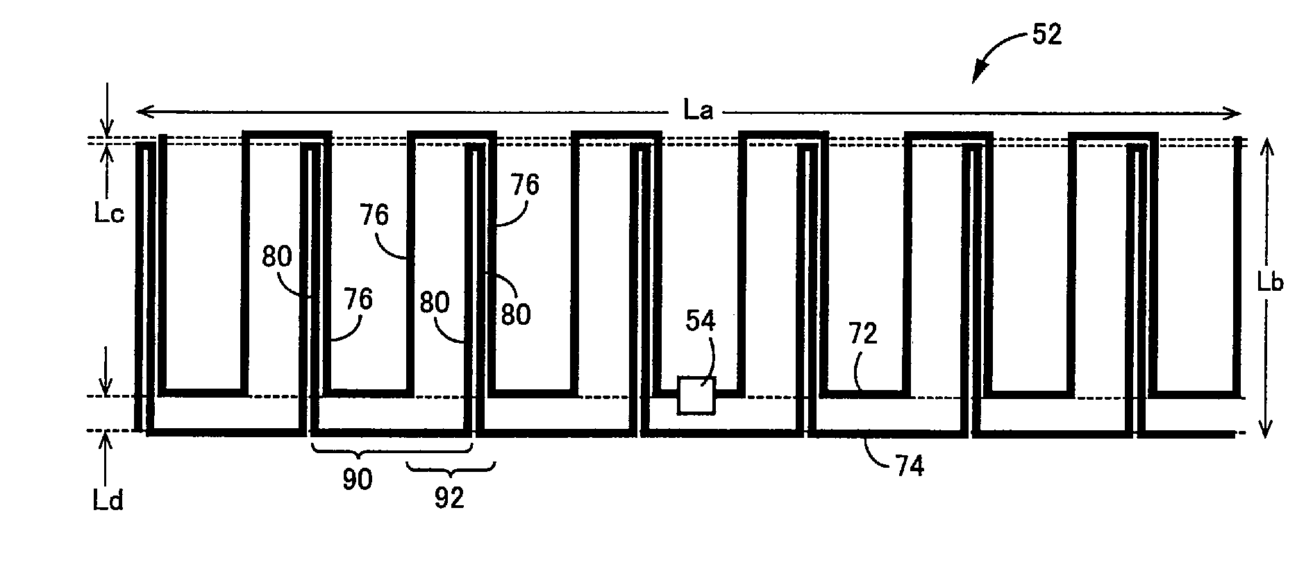
[0115]Referring to the plan view of FIG. 25, there is shown an arrangement of an antenna 96 constructed according to this invention. Like the antenna 52 described above, this antenna 96 includes a driven meander line portion 98 and a parasitic meander line portion 100. The driven meander line portion 98 consists of the transverse conductive sections 76 and the longitudinal conductive sections 78 which are alternately connected to each other, so as to form a meandering or serpentine pattern, while the parasitic meander line portion 100 consists of the transverse conductive sections 80 and the longitudinal conductive sections 82, 84 which are alternately connected to each other so as to form a meandering or serpentine pattern. The driven and parasitic meander line portions 98, 100 are positioned relative to each other such that the adjacent two transverse conductive sections 80 of the parasitic meander line portion 100 which are spaced apart from each other by a comparatively small di...

third embodiment

[0118]Referring next to the plan view of FIG. 27, there is shown an arrangement of an antenna 104 constructed according to this invention. This antenna 104 includes a driven meander line portion 106 which is a line conductor formed in a meandering pattern, and a parasitic meander line portion 108 which is also a line conductor formed in a meandering pattern. Each of the driven and parasitic meander line portions 106, 108 consists of a plurality of transverse conductive sections 110, a plurality of long longitudinal conductive sections 112 and a plurality of short longitudinal conductive sections 114. The transverse conductive sections 110 and the longitudinal conductive sections 112, 114 are alternately connected to each other, so as to form a meandering or serpentine pattern. As shown in FIG. 27, the adjacent two transverse conductive sections 110 of the parasitic meander line portion 108 are interposed between the corresponding adjacent two transverse conductive sections 110 of th...


PUM


Abstract

An antenna connected to a circuit portion and configured to effect transmission and reception of information by radio communication, the antenna including a driven meander line portion which has a feed section connected to the circuit portion and which is a line conductor formed in a meandering pattern, and a parasitic meander line portion which does not have a feed section connected to the circuit portion and which is a line conductor formed in a meandering pattern and positioned relative to the driven meander line portion, so as to influence an input impedance of the driven meander line portion. Also disclosed is a radio-frequency identification tag including the antenna.

Description

CROSS REFERENCE TO RELATED APPLICATIONS[0001]The present application is a Continuation-in-Part of International Application No. PCT / JP2006 / 310593 filed May 26, 2006, which claims the benefits of Japanese Patent Application No. 2005-212450 filed Jul. 22, 2005, and Japanese Patent Application No. 2006-007800 filed Jan. 16, 2006, the disclosure of which is herein incorporated by reference in its entirety.BACKGROUND OF THE INVENTION[0002]1. Field of the Invention[0003]The present invention relates to improvements of an antenna suitably used for a radio-frequency identification tag capable of writing and reading information in a non-contact fashion.[0004]2. Description of Related Art[0005]There is known an RFID (Radio-Frequency Identification) communication system wherein a radio-frequency tag communication device (interrogator) reads out information, in a non-contact fashion, from small-sized radio-frequency identification tags (transponders) on which desired information is written. In ...

Claims


Application Information

Patent Timeline
Patent Type & Authority Patents(United States)
IPC IPC(8): H01Q1/36
CPCH01Q1/2225H01Q1/38H01Q1/2208
Inventor TAKI, KAZUNARIMIYAZAKI, YASUMITSU
Owner BROTHER KOGYO KK
Why Eureka
Try Eureka