Terminating a non-clustered workload in response to a failure of a system with a clustered workload

a technology of clustered workload and workload, which is applied in the direction of instruments, error detection/correction, computing, etc., can solve the problem of high cost of over-provisioning

Active Publication Date: 2010-01-26
HEWLETT-PACKARD ENTERPRISE DEV LP
View PDF9 Cites 76 Cited by
  • Summary
  • Abstract
  • Description
  • Claims
  • Application Information

AI Technical Summary

Problems solved by technology

To avoid this, each partition in a cluster can have sufficient resources to run an extra workload, but this type of over-provisioning can be expensive.

Method used


Image

  • Terminating a non-clustered workload in response to a failure of a system with a clustered workload
  • Terminating a non-clustered workload in response to a failure of a system with a clustered workload
  • Terminating a non-clustered workload in response to a failure of a system with a clustered workload

Examples


Embodiment Construction

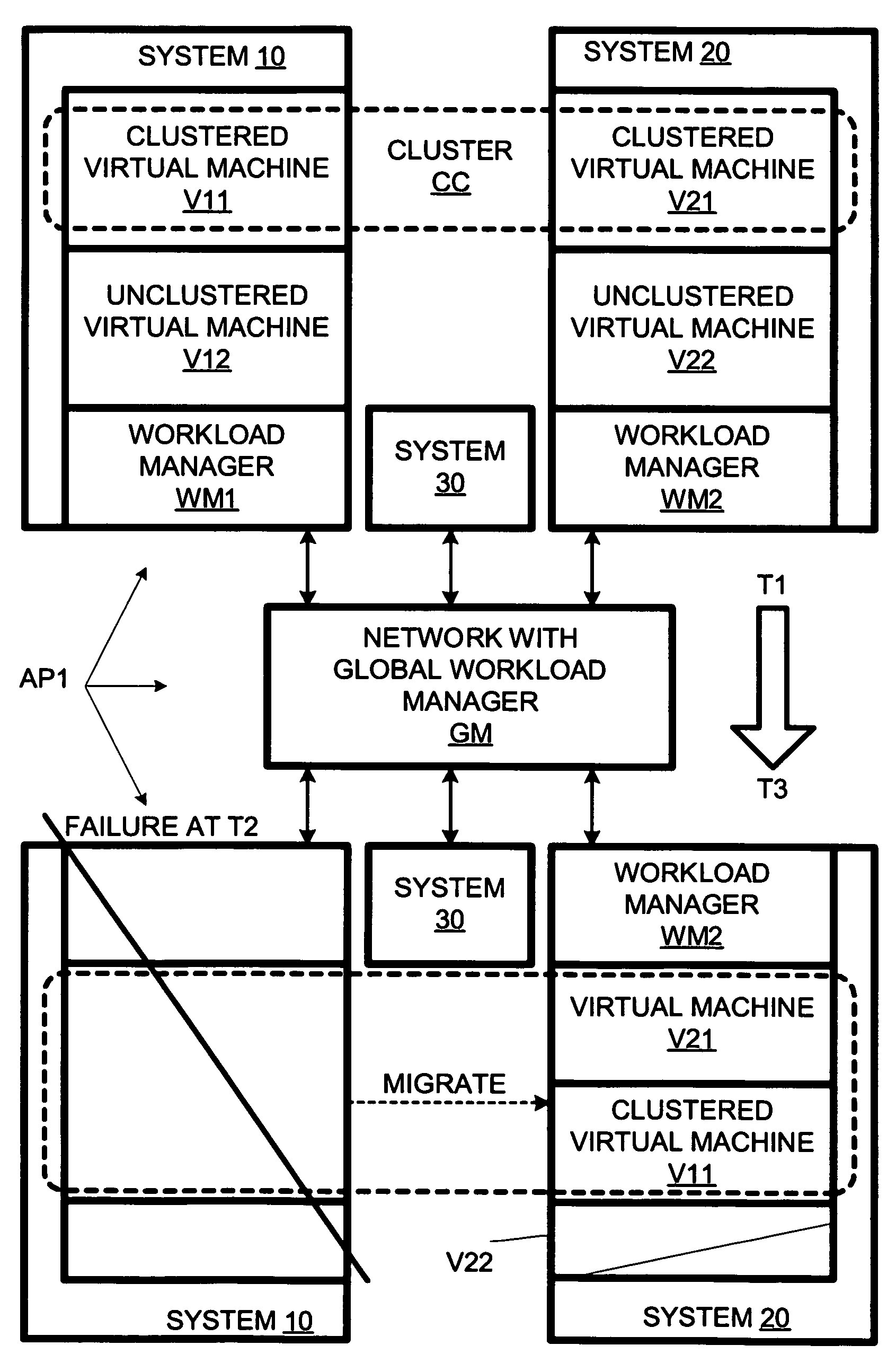
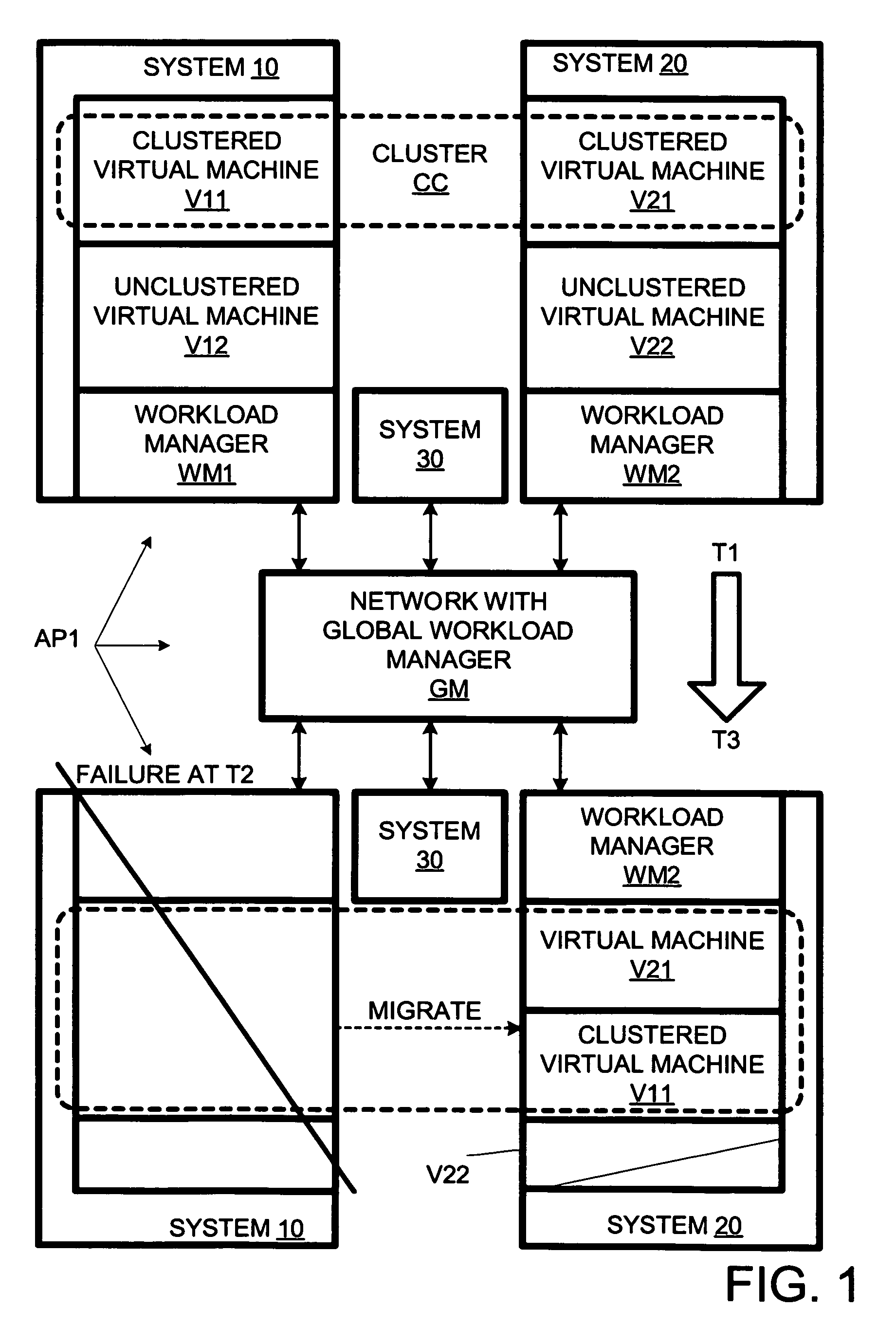
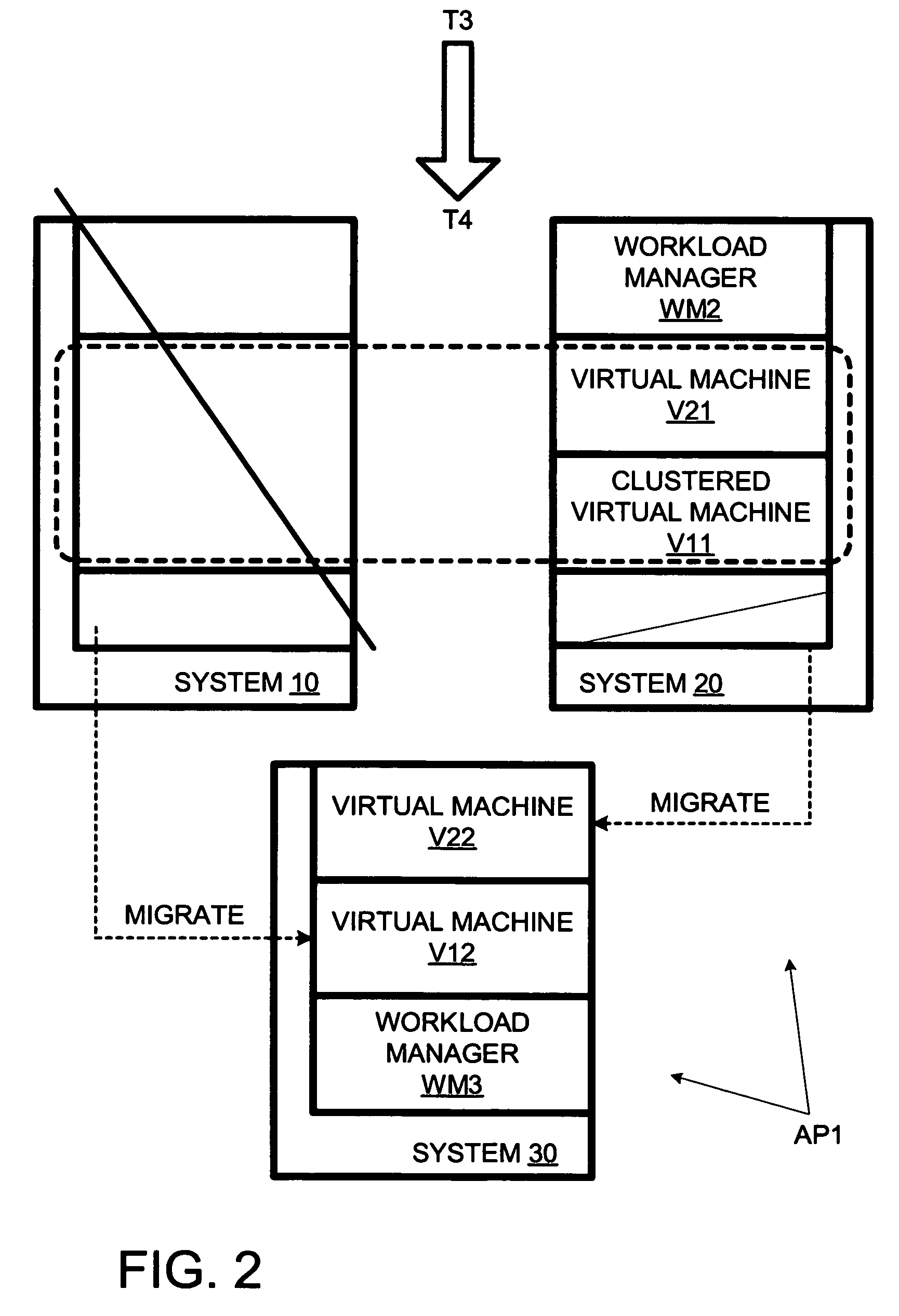
[0007]FIGS. 1 and 2 depict a network AP1 having clustered computer systems 10 and 20 and an unclustered computer system 30. The remainder of network AP1 includes a global workload manager GM, which can be a management workstation. Computer systems 10 and 20 are shown at the top of FIG. 1 in respective configurations at a pre-failure time T1 prior to a failure at a time T2. Computer systems 10 and 20 are shown at the bottom of FIG. 1 in respective configurations at a post-failure time T3.

[0008]At pre-failure time T1, system 10 is configured so that it is running a workload manager WM1 and two virtual machines V11 and V12. Also at pre-failure time T2, system 20 is configured so that it is running a workload manager WM2, and virtual machines V21 and V22. Systems 10 and 20 are clustered so that virtual machines V11 and V21 are in a common cluster CC. Virtual machines V12 and V22 are not in clusters. Herein, each virtual machine defines a respective partition.

[0009]As used herein and app...


PUM


Abstract

The present invention provides for check-pointing an non-clustered workload to make room for a clustered workload that was running on a computer system that has suffered a hardware failure.

Description

BACKGROUND OF THE INVENTION[0001]Herein, related art may be discussed to put the invention in context. Related art labeled “prior art” is admitted prior art; related art not labeled “prior art” is not admitted prior art.[0002]In a high-availability computer system, upon failure of a clustered partition, its workload is typically transferred to another partition in that cluster. However, as the destination partition may already be running its own workload, the migration can result in adequate resources for the combination of the old and the migrated workload. To avoid this, each partition in a cluster can have sufficient resources to run an extra workload, but this type of over-provisioning can be expensive. The present invention provides for a more effective reallocation of resources in response to a failure of a clustered system. This provides an economic advantage since fewer spare resources are required to handle a system failure.BRIEF DESCRIPTION OF THE DRAWINGS[0003]The followi...

Claims


Application Information

Patent Timeline
Patent Type & Authority Patents(United States)
IPC IPC(8): G06F11/00
CPCG06F11/2035G06F11/1438G06F11/203G06F2201/815
Inventor MILLER, TROY DONCRAWFORD, JR., ISOM LAWRENCE
Owner HEWLETT-PACKARD ENTERPRISE DEV LP
Why Eureka
Try Eureka