Vehicular lamp

a technology for lamps and tubes, applied in fixed installations, lighting and heating equipment, lighting support devices, etc., to achieve the effect of improving the overall outer appearance of lamps

Inactive Publication Date: 2010-02-02
KOITO MFG CO LTD
View PDF7 Cites 23 Cited by
  • Summary
  • Abstract
  • Description
  • Claims
  • Application Information

AI Technical Summary

Benefits of technology

[0010]It is, therefore, an object of the present invention to provide a vehicular lamp that is capable of providing a desired light distribution pattern when a second light source thereof is lit, while also improving the overall outer appearance of the lamp without exposing the second light source.
[0011]It is another object of the present invention to provide a vehicular lamp that is capable of suppressing a temperature increase of the lamp.
[0013]As seen from the above, according to the present invention, the second light source is provided on the rear side of the shade, which is an opposite side from the projection lens, and the light transmission portion (a through hole) is formed in the shade so that light from the second light source passes therethrough to the projection light. Accordingly, light flux from the light transmission portion can be controlled so that the lamp is able to provide a desired light distribution pattern. Furthermore, since the rear side of the shade is dark as it is difficult for external light to reach, the second light source is not exposed through the projection lens or the light transmission portion and thus not seen from the outside of the lamp (through the projection lamp). Accordingly, the lamp has an improved overall outer appearance.
[0014]In the present invention, the second light source is formed by a semiconductor light-emitting element. Accordingly, heat generated by the second light source can be suppressed, and a temperature increase of the lamp is prevented accordingly. Since the first light source is also formed by a semiconductor light-emitting element, heat generated by the first light source is suppressed as well, and a temperature increase of the lamp is further prevented accordingly.
[0015]In the present invention, the light source unit comprises the first light source and the second light source, and these light sources are provided on a heat block for releasing the heat generated by the respective light sources. Accordingly, heat generated by the first and second light sources can be easily and effectively released, and as a result, the temperature increase of the lamp is sufficiently prevented.

Problems solved by technology

Furthermore, since the rear side of the shade is dark as it is difficult for external light to reach, the second light source is not exposed through the projection lens or the light transmission portion and thus not seen from the outside of the lamp (through the projection lamp).

Method used


Image

  • Vehicular lamp
  • Vehicular lamp
  • Vehicular lamp

Examples


first embodiment

[0022]FIG. 1 is a cross-sectional view of the first embodiment in which the present invention is applied to a fog lamp of an automobile.

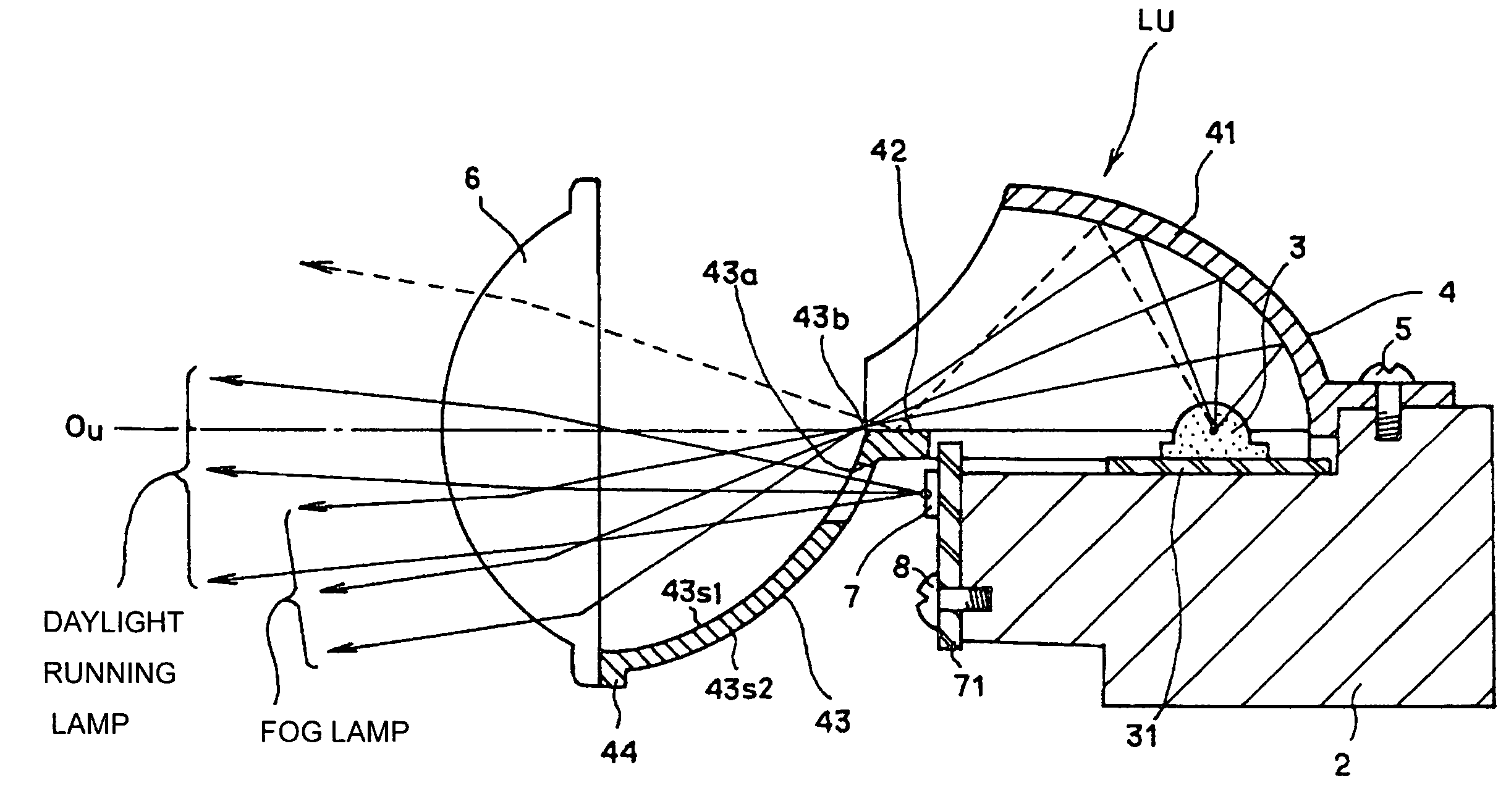
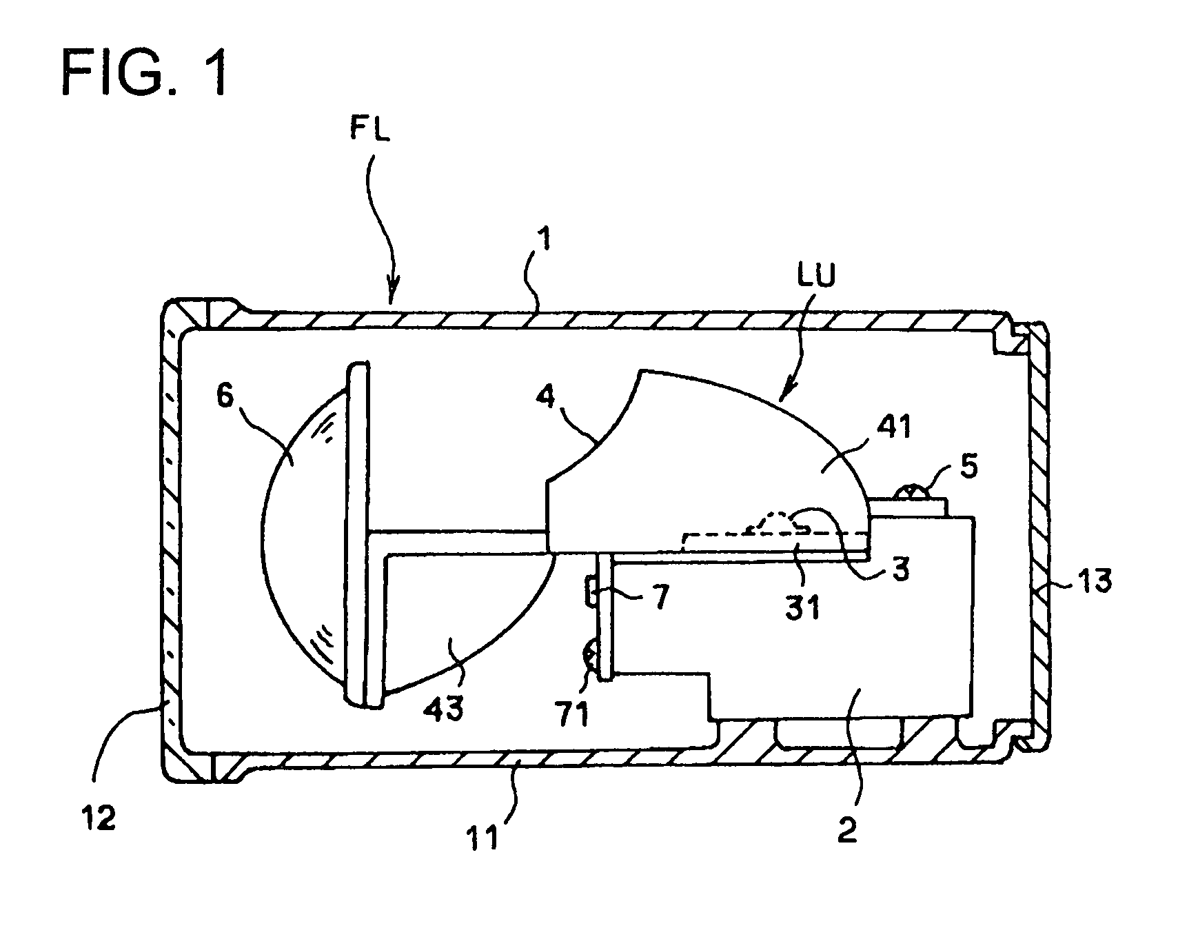
[0023]The fog lamp FL is used in combination as a daytime running lamp for increasing the visibility of the host vehicle, i.e., increasing the visibility performance of the vehicle that is mounted with the fog lamp FL, so as to be easily recognized by other vehicles in the daytime. The fog lamp FL has a configuration in which the lamp housing 1 is formed by a lamp body 11, a transparent cover 12 that is attached to the front opening of the lamp body 11, and a back cover 13 that covers the back opening of the lamp body 11; and mounted inside the lamp housing 1 is a single light source unit LU that includes a semiconductor light-emitting element. In the shown embodiment, the semiconductor light-emitting element is a light-emitting diode (LED).

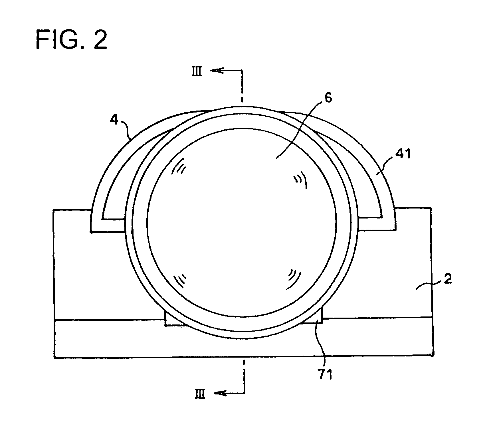
[0024]More specifically, as shown respectively in a frontal view in FIG. 2, a vertical cross-sectional view al...

second embodiment

[0040]Meanwhile, when the fog lamp of the second embodiment is used as a clearance lamp, only the second LED 7 is lit to emit light. Light irradiated from the second LED 7 is reflected by the concaved surface on the lower side of the sub-reflector 42A so as to be oriented slightly upward of the general horizontal direction and passes through the shade opening 43a to advance forward; and such light is slightly condensed by the projection lens 6 and irradiated forward from the projection lens 6 while being oriented slightly upward of the unit optical axis Ou. Light flux irradiated through the shade opening 43a can be controlled by (the size and shape of) the shade opening 43a, and thus it is possible for the fog lamp to provide a desired light distribution pattern.

[0041]Thus, the fog lamp of the second embodiment functions as a clearance lamp that provides a desired light distribution pattern, and this can be achieved by suitably designing the (size and shape of) shade opening 43a of ...


PUM


Abstract

A vehicular lamp with a light source unit that includes a main reflector for reflecting light irradiated from a first light source, a projection lens that condenses and radiates light reflected by the main reflector, and a shade that blocks a part of the light reflected by the main reflector, wherein the light source unit further includes a second light source, which is disposed on the opposite side from the projection lens provided on the shade, and the shade is formed with a light transmission portion which is an opening that allows the light irradiated from the second light source to pass therethrough to the projection lens.

Description

BACKGROUND OF THE INVENTION[0001]1. Field of the Invention[0002]The present invention relates to a vehicular lamp having a projection lens that condenses light irradiated from the light source and more particularly to a vehicular lamp further provided with a second light source.[0003]2. Description of the Related Art[0004]Lamps known as projector-type lamps have recently been used as front lamps (headlamps) and auxiliary lamps (fog lamps) for automobiles. Such projector-type lamps generally include a projection lens that is formed by a condenser lens and is provided in front of the light source; and in such projector-type lamps, light irradiated from the light source is reflected by a reflector and condensed at a rear-side focal point of the projection lens or a nearby position thereof, so that the condensed light is projected by the projection lens. This type of projector-type lamps provide a wide illumination range while enabling downsizing of the light irradiation surface on the ...

Claims


Application Information

Patent Timeline
Patent Type & Authority Patents(United States)
IPC IPC(8): B60Q1/04F21V11/00
CPCB60Q1/0041F21S48/1159F21S48/145F21S48/328F21V17/12F21V29/004F21Y2101/02F21Y2115/10F21S41/43F21S45/47F21V29/70F21S41/148B60Q1/04F21V14/00
Inventor MOCHIZUKI, KAZUHISAOHISHI, MASAFUMI
Owner KOITO MFG CO LTD
Why Eureka
Try Eureka