Calibrating a defect scan parameter for a disk drive

a technology of defect scan and disk drive, applied in the field of disk drives, can solve problems such as defect detection, unusable disk surface parts,

Inactive Publication Date: 2010-02-02
WESTERN DIGITAL TECH INC
View PDF10 Cites 150 Cited by
  • Summary
  • Abstract
  • Description
  • Claims
  • Application Information

AI Technical Summary

Problems solved by technology

Various influences may render portions of the disk surface unusable (i.e., defective), for example, if the magnetic coating is not evenly applied to the disk surface or if a particle contaminates the magnetic coating.
If the quality metric falls below a predetermined defect scan threshold, a defect is detected.
If a defective data sector is not detected during the defect scan procedure, there is a risk of catastrophic data loss, either immediately, or over time as the uniform alignment of the magnetic grains deteriorates (magnetic entropy).
Conversely, if the defect scan threshold is set too low in an attempt to detect more defective data sectors, more good data sectors will be identified as defective and mapped out unnecessarily, thereby reducing the capacity and performance of the disk drive.

Method used


Image

  • Calibrating a defect scan parameter for a disk drive
  • Calibrating a defect scan parameter for a disk drive
  • Calibrating a defect scan parameter for a disk drive

Examples


Embodiment Construction

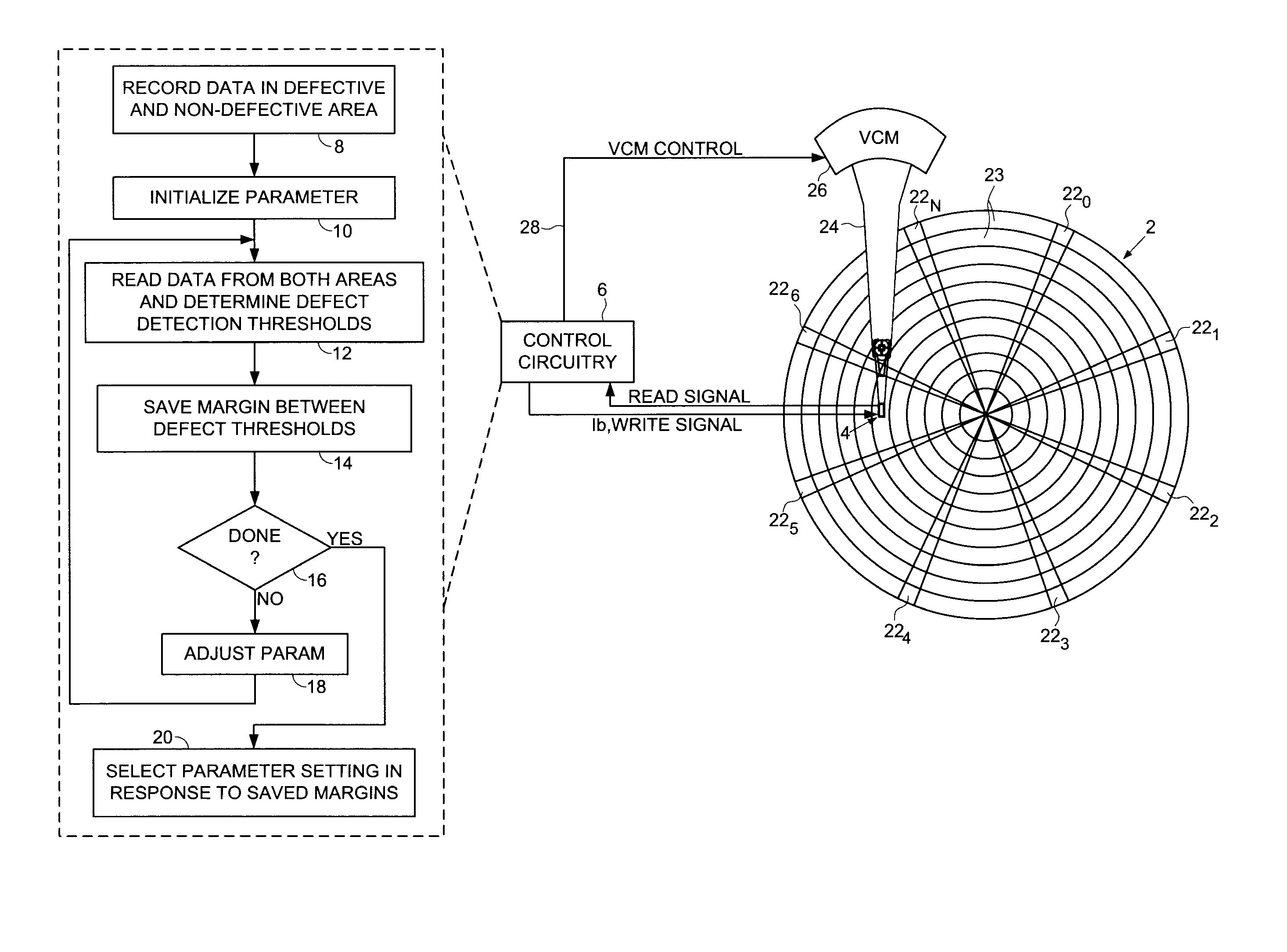
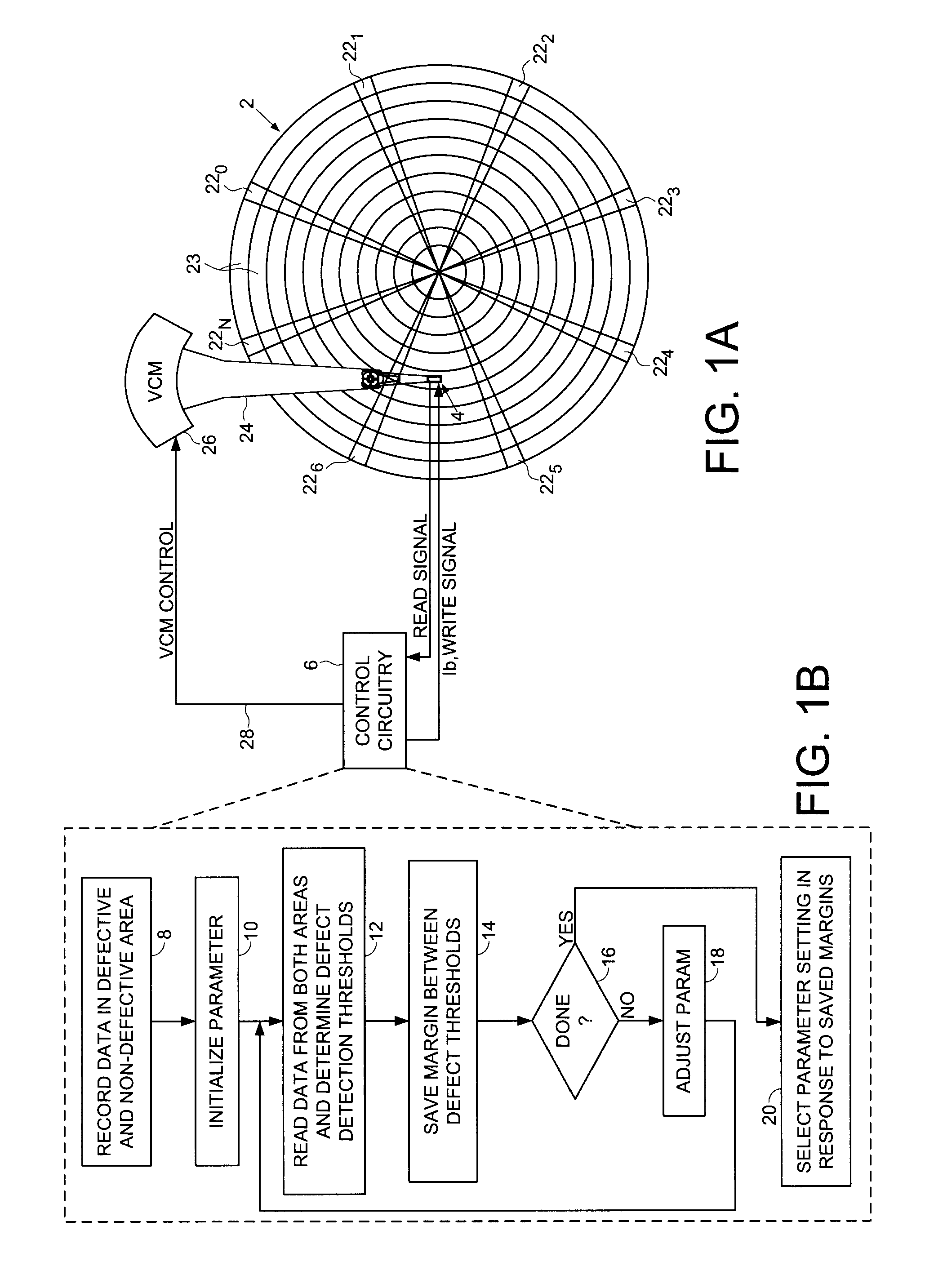
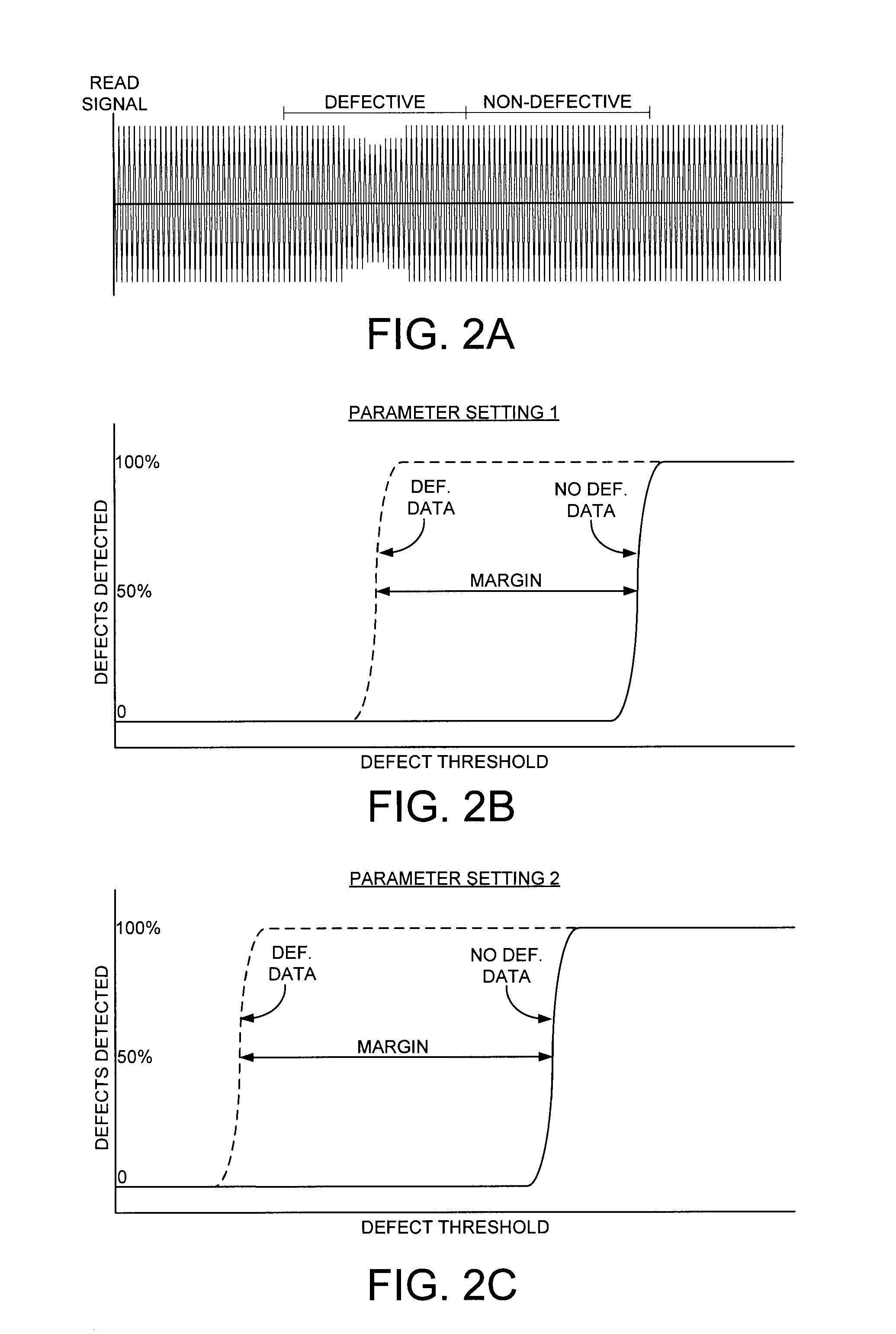
[0007]An embodiment of the present invention comprises a method of performing a defect scan for a disk drive, the disk drive comprising a disk, and a head actuated over the disk. Data is recorded on a first data area of the disk substantially free from defects and on a second data area of the disk substantially affected by at least one defect. A defect scan parameter is initialized with an initial setting. The first data area is read to determine a first defect threshold, and the second data area is read to determine a second defect threshold. A margin is saved representing a difference between the first and second defect thresholds. The setting for the defect scan parameter is adjusted, and the elements of reading the first and second data areas and saving a corresponding margin are repeated at least once. A first setting is then selected for the defect scan parameter in response to the saved margins.

[0008]In one embodiment, the first setting selected for the defect scan parameter ...


PUM

PropertyMeasurementUnit
defectaaaaaaaaaa
defect thresholdaaaaaaaaaa
defect thresholdsaaaaaaaaaa

Abstract

A method is disclosed for performing a defect scan for a disk drive. Data is recorded on a first data area of a disk substantially free from defects and on a second data area of the disk substantially affected by at least one defect. A defect scan parameter is initialized with an initial setting. The first data area is read to determine a first defect threshold, and the second data area is read to determine a second defect threshold. A margin is saved representing a difference between the first and second defect thresholds. The setting for the defect scan parameter is adjusted, and the elements of reading the first and second data areas and saving a corresponding margin are repeated at least once. A setting is then selected for the defect scan parameter in response to the saved margins.

Description

BACKGROUND[0001]1. Field[0002]The present invention relates to disk drives for computer systems. In particular, the present invention relates to calibrating a defect scan parameter for a disk drive.[0003]2. Description of the Related Art[0004]The disk in a disk drive is coated with a magnetic material which is magnetized with a write element (e.g., a write coil) in order to record information onto the surface of the disk. Various influences may render portions of the disk surface unusable (i.e., defective), for example, if the magnetic coating is not evenly applied to the disk surface or if a particle contaminates the magnetic coating. During a manufacturing “defect scan” procedure, the defective areas of the disk are located and “mapped out” so they are not used during normal operation. The defect scan typically entails writing a high frequency pattern (e.g., a 2T pattern) to the disk, and then reading the high frequency pattern while monitoring a quality metric, such as an amplitu...

Claims


Application Information

Patent Timeline
Patent Type & Authority Patents(United States)
IPC IPC(8): G11B5/09
CPCG11B5/09
Inventor JIN, MINGYEO, TEIK EE
Owner WESTERN DIGITAL TECH INC
Why Eureka
Try Eureka