Compression device and method for adjustment of a compression pressure

a compression device and compression pressure technology, applied in the field of compression devices and compression pressure adjustment methods, can solve problems such as pain in the breast during compression, and achieve the effect of improving the spatial resolution of this method and sufficient spatial resolution

Inactive Publication Date: 2010-02-02
SIEMENS HEALTHCARE GMBH
View PDF14 Cites 42 Cited by
  • Summary
  • Abstract
  • Description
  • Claims
  • Application Information

AI Technical Summary

Benefits of technology

[0010]By using a number of elastically-deformable compression plate elements, the physical structure of the subject to be compressed can be better accommodated. “A number of compression plate elements” means at least two compression plate elements. The number of compression plate elements can be moved relative to one another, so the compression plate can adapt to a shape of a subject. Furthermore, the compression plate elements can be coupled with one another with coupling components. The shape of the compression plate elements that can be set (selected) arbitrarily. A good adaptation of the shape of the compression plate to that of the respective contour of the subject to be compressed, such as the anatomy of a female breast, can be achieved during the compression of the subject to be compressed by the multiple elastically-deformable compression plate elements.
[0041]In an embodiment of the inventive method a compression pressure distribution of the subject to be compressed is determined during the compression from the compression pressures detected for the subject to be compressed by a number of sensors arranged at different positions and / or in different orientations on at least one compression plate element. A pressure distribution for the subject to be compressed can be determined using the compression pressures detected by these sensors. With the use of multiple pressure sensors, a sufficient spatial resolution can be achieved in order to be able to make diagnostic conclusions with regard to a local or global pressure maximum that results, for example, from the presence of a nodule in a female breast. To improve the spatial resolution of this method, interpolation methods can be used.

Problems solved by technology

In mammography the compression by means of a rigid compression plate often causes pain in the breast during the compression.

Method used


Image

  • Compression device and method for adjustment of a compression pressure
  • Compression device and method for adjustment of a compression pressure
  • Compression device and method for adjustment of a compression pressure

Examples


Embodiment Construction

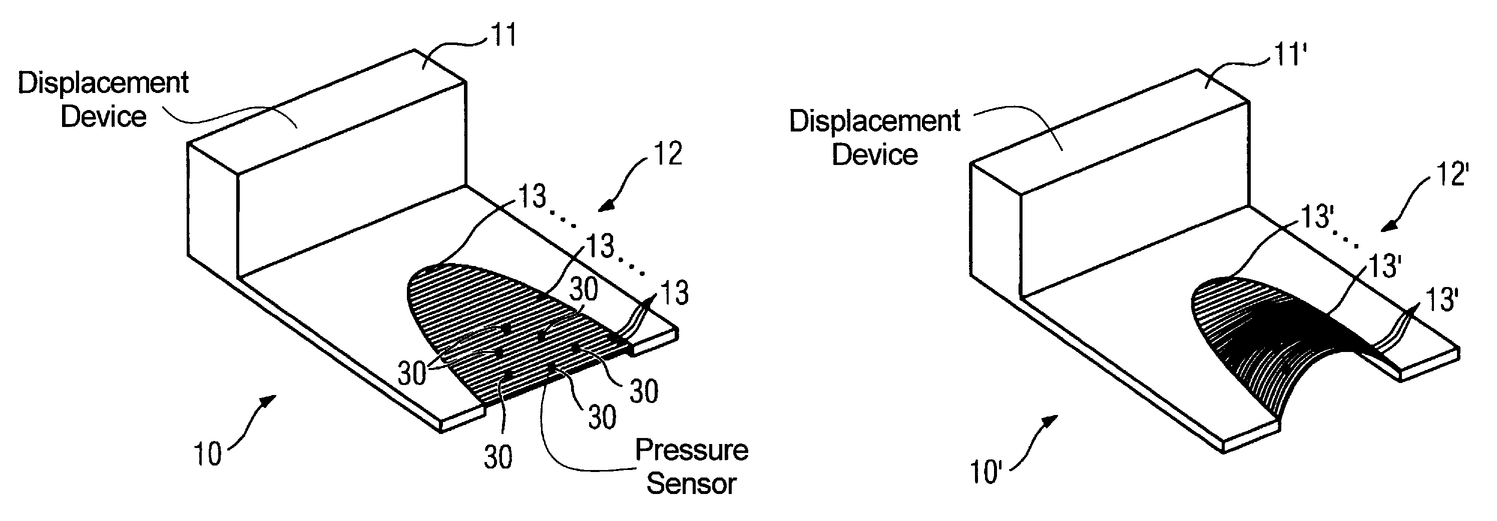
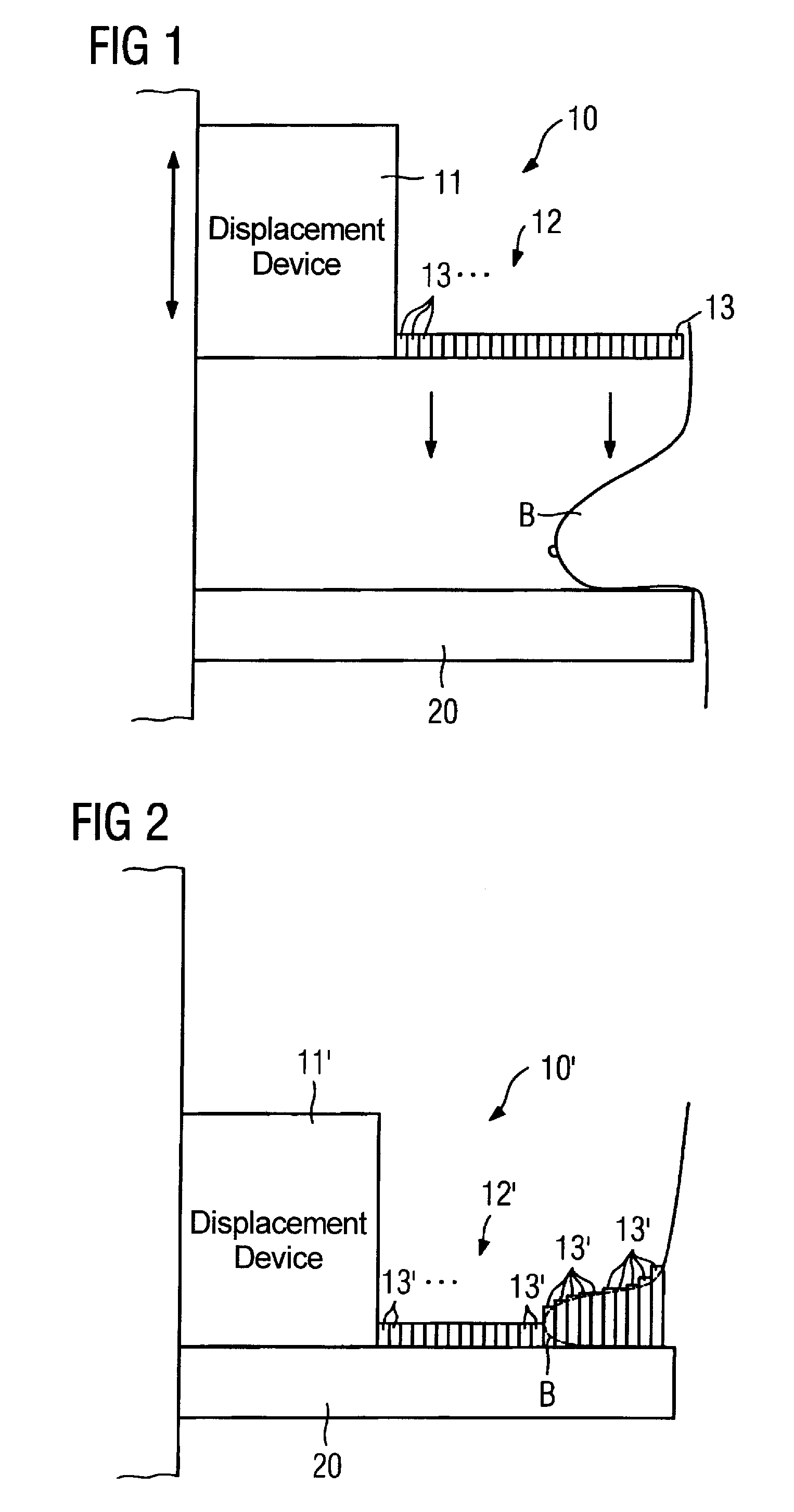
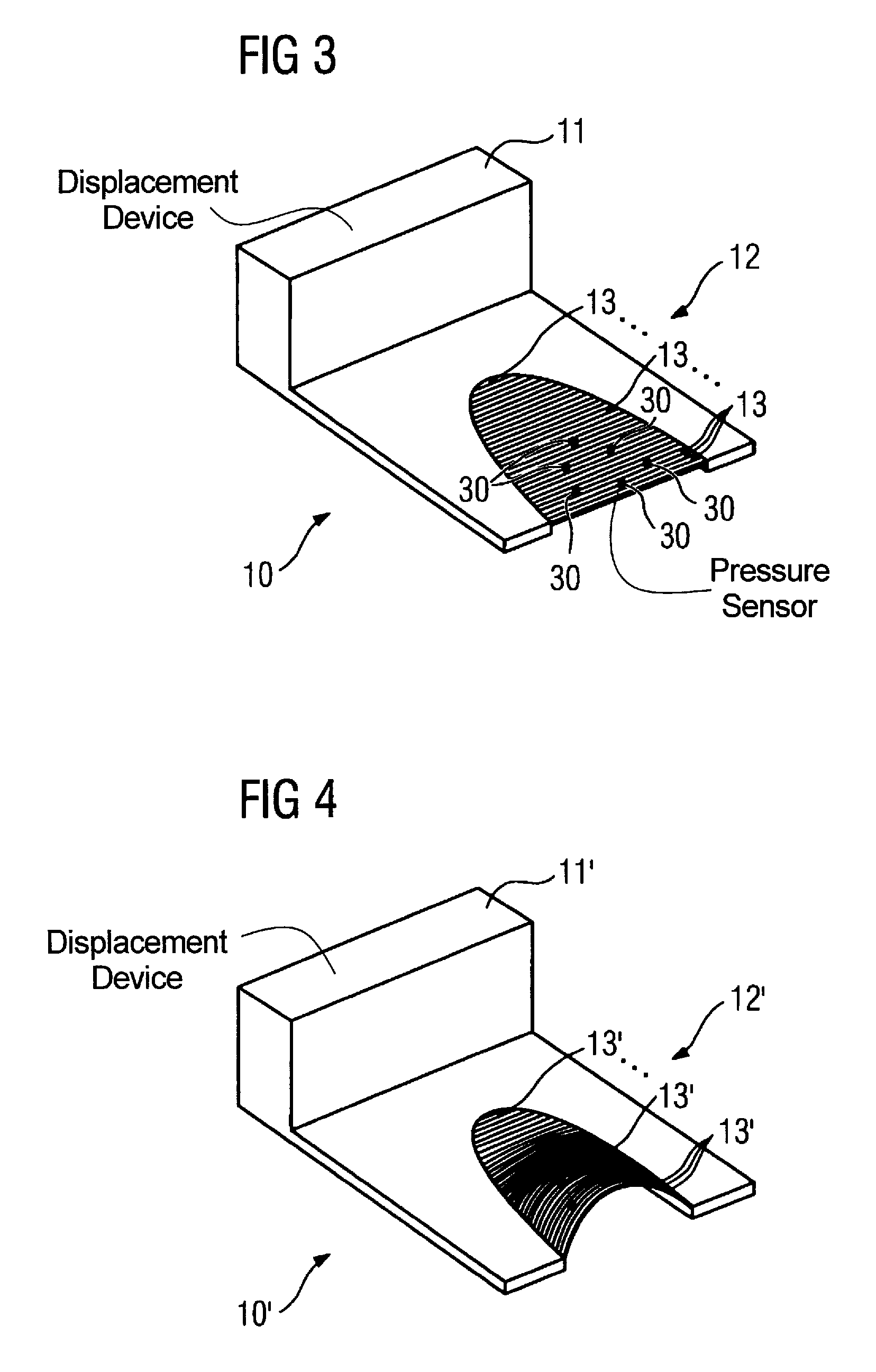
[0051]FIG. 1 shows a side view of a compression device 10 that includes a displacement device 11 and a compression plate 12. Additionally shown is a support table 20 on which is arranged a subject B to be compressed. The subject B to be compressed in FIG. 1 is a female breast of an examination subject. FIG. 1 shows an arrangement for compression of the female breast B, the breast B being arranged between the compression plate 12 and support table 20.

[0052]The compression device 10 can be displaced in the vertical direction relative to the support table 20. Decreasing the spacing between the compression plate 12 and the support table 20 can be achieved by a displacement of the displacement device 11 together with the compression plate 12 relative to the support 20. At a certain distance (predetermined by the anatomy of the breast B), the surface of the breast B is contacted and compressed with the compression plate 12 upon further displacement of the displacement device 11 together w...


PUM


Abstract

A compression device has a compression plate that applies a pressure to a subject on a support plate. The compression plate has a number of elastically-deformable compression plate elements that are substantially transparent for an examination field used with the compression device. In a method for compressing a subject, at least one pressure sensor measures the pressure applied by a compression device to a subject, and wirelessly supplies a signal representing the detected pressure to a control unit, wherein the detected pressure is compared to a stored compression pressure value. The control device adjusts the pressure applied to the subject by the compression device so that the pressure detected by the sensor is equal to the stored compression pressure value.

Description

BACKGROUND OF THE INVENTION[0001]1. Field of the Invention[0002]The present invention concerns a compression device and a method for adjustment of a compression pressure.[0003]2. Description of the Prior Art[0004]Compression devices are used in many technical fields in which it is necessary, for example, to compress an object or a number of objects, to adjust the thickness of an object, or to seal a leak of an object. Possible technical fields are, among other things, material sciences, food monitoring and medical technology.[0005]Compression devices are used in the medical field in, among other things, mammography and for biopsy procedures. A compression device normally has a compression plate provided for compression of the subject to be examined (the female breast in the case of mammography). Today the compression is normally implemented with rigid, inflexible compression plates. The compression device together with the rigid compression plate is displaced relative to a bearing t...

Claims


Application Information

Patent Timeline
Patent Type & Authority Patents(United States)
IPC IPC(8): A61B6/04
CPCA61B6/0414A61B6/502
Inventor HOERNIG, MATHIAS
Owner SIEMENS HEALTHCARE GMBH
Why Eureka
Try Eureka