Engine air intake and fuel chilling system and method

Inactive Publication Date: 2010-02-09
SUPERCOOLER
View PDF18 Cites 25 Cited by
  • Summary
  • Abstract
  • Description
  • Claims
  • Application Information

AI Technical Summary

Problems solved by technology

Although such devices may be effective to some degree there is no supportin

Method used


Image

  • Engine air intake and fuel chilling system and method
  • Engine air intake and fuel chilling system and method
  • Engine air intake and fuel chilling system and method

Examples


Example

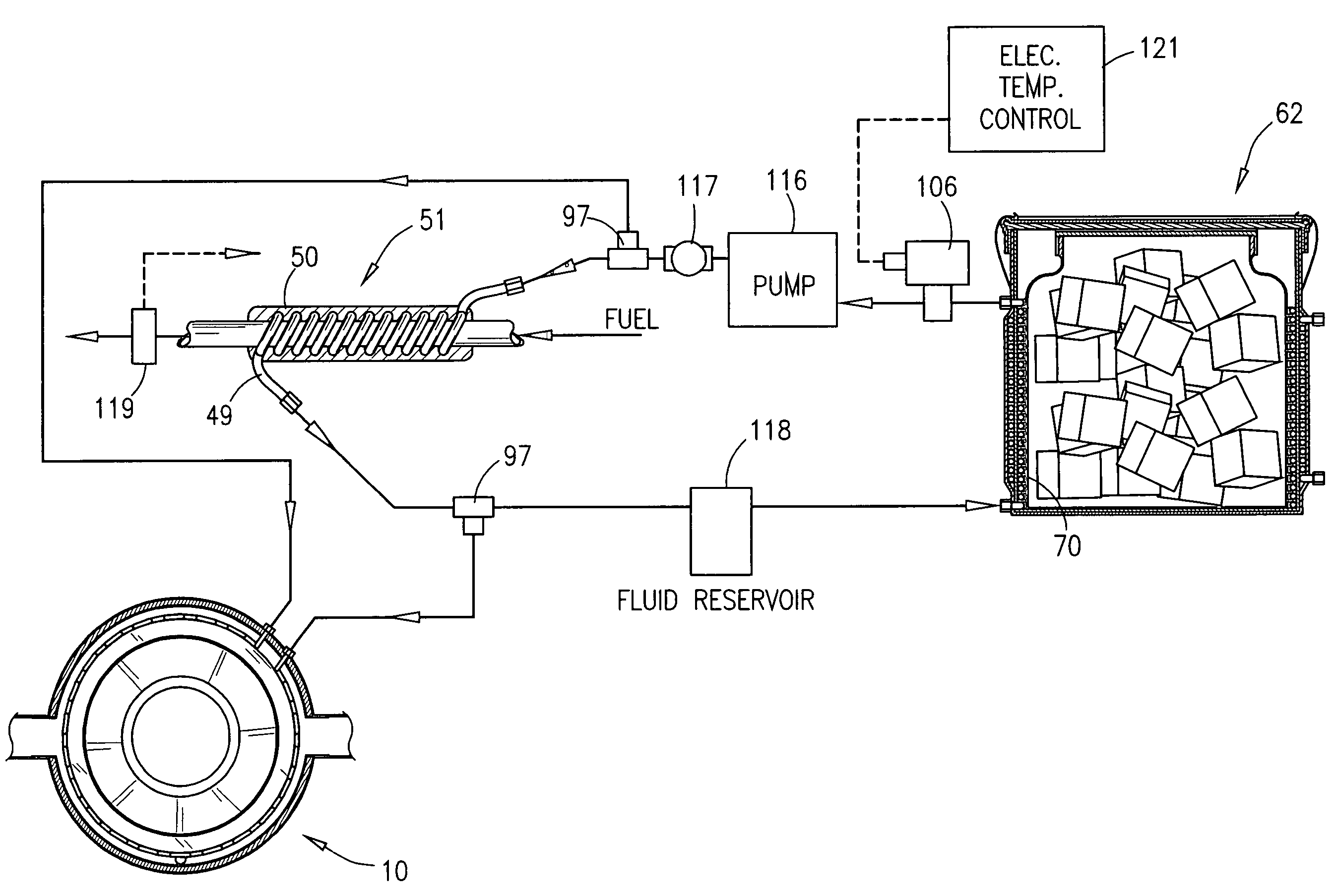
[0023]The engines eluded to herein are considered to be naturally aspirated engines with carburetors or fuel injection.

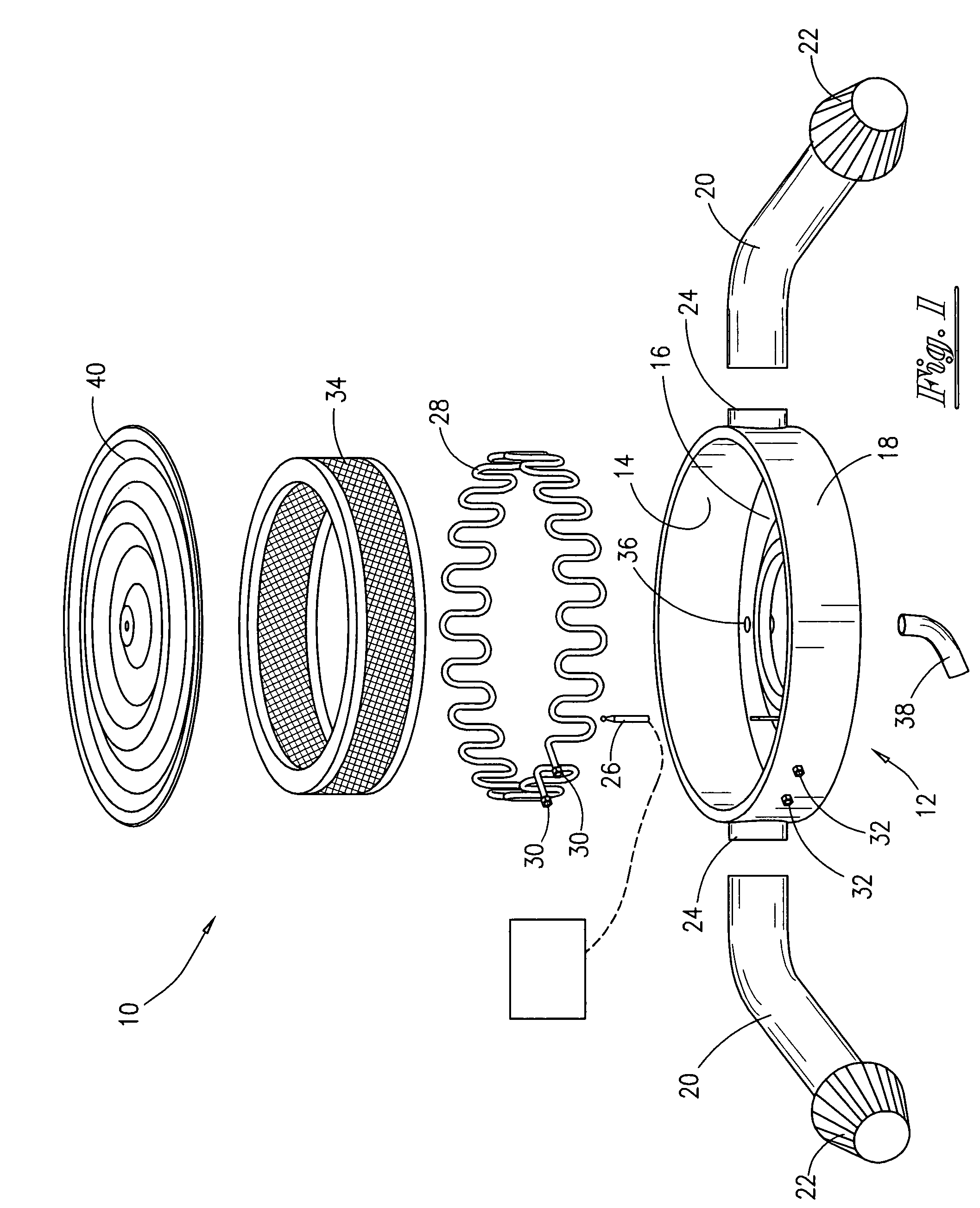
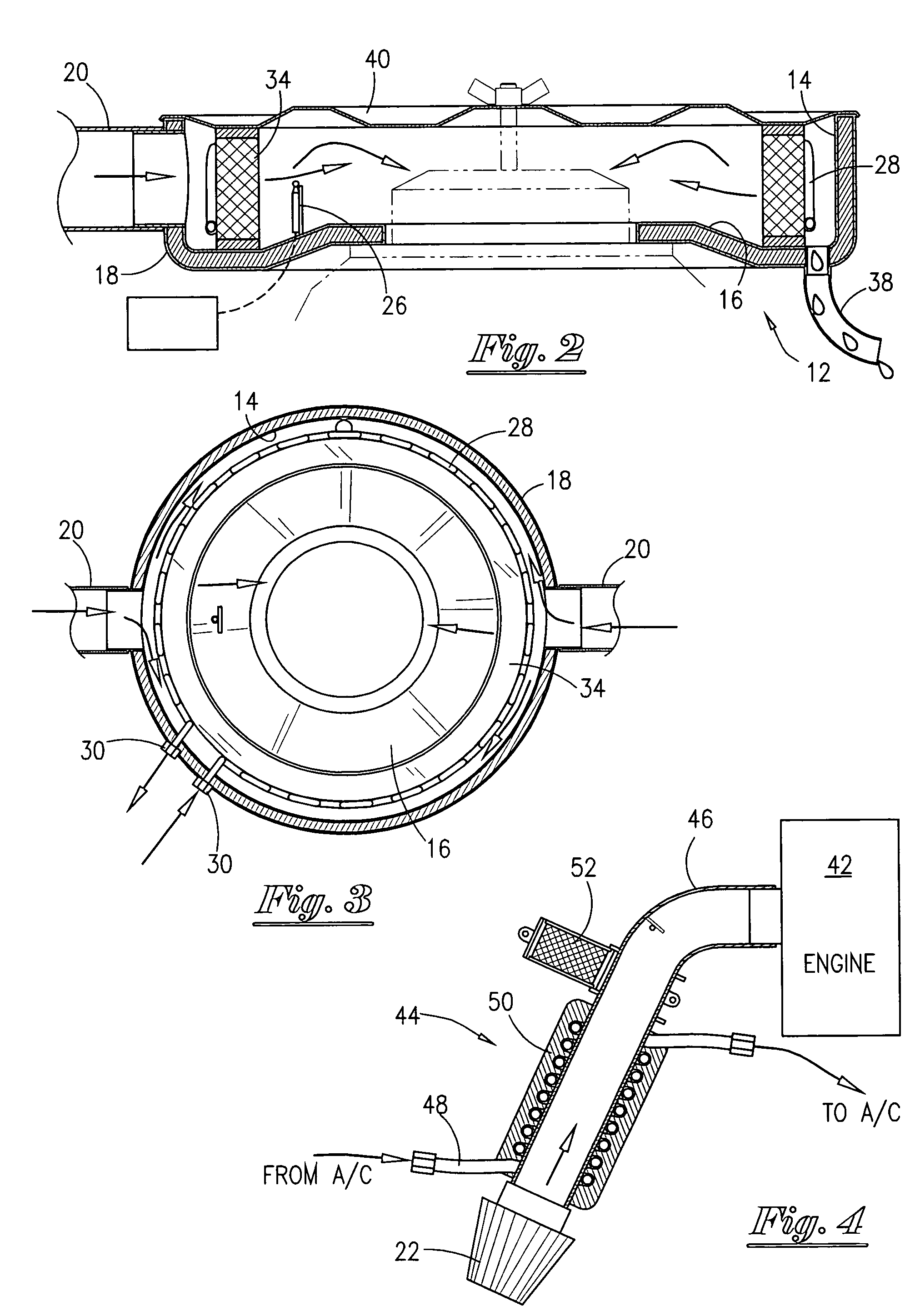
[0024]Looking first at FIG. 1 the carburetor air breather assembly 10 includes a container assembly 12 with a circular vertical wall 14 and a floor or catch basin 16 having a opening therein removably adapted to seal ably fit and cover the intake throat of an engine carburetor in the commonly accepted practice. The exposed exterior of the container assembly 12 is fully covered with an insulating material 18. Container assembly 12 may also be fitted with one or more air intake ducts 20 fitted with filters 22 at one end. One or more air intake ducts 20 may be attached to the ports 24. In cases where only one intake duct 20 is used any remaining ports 24 may remain sealed. Such intake ducts 20 are generally referred to (in the high performance accessories market) as cold air intake ducts used for rerouting intake air from within the engine bay to some point outside the...


PUM


Abstract

A combustion engine intake air cooler system is disclosed that utilizes the vehicle air conditioning system to chill the engine intake air supply by conducting latent heat from the intake air passing through the intake air ducts using an external tubular induction coil in contact with and surrounding the air intake duct and connected to the vehicle air conditioning refrigeration system. Other embodiments include a refrigeration conduction coil located within a sealed and insulated, carburetor air breather and a refrigeration conduction coil in contact with the engine fuel line. An on board refrigerator using dry ice is also disclosed as a refrigeration system for the conduction coils when no vehicle air conditioning system is available. An intake air temperature sensing and control system is also provided.

Description

1. FIELD OF THF INVENTION[0001]This invention relates generally to automobile engine cold air intakes and more particularly to the super chilling of the air being drawn into the engine by natural aspiration and the chilling of engine fuel.2. GENERAL BACKGROUND[0002]So called cold air engine intake products are designed to reroute intake air to the engine from a location outside the engine compartment. Such cold air intake tubes do reduce the temperature of the air entering the engine, through the carburetor or injection manifold. As a result of the differential between engine compartment temperature and the ambient temperature at speed the reduction is usually between 40 and 50 degrees. However, the engine intake air is only reduced to a percentage of the differential temperature, thus the true intake air temperature is generally about half of the differential temperature.[0003]It is well known within the art that such cold air intake tubes are advantageous for engine performance. C...

Claims


Application Information

Patent Timeline
IPC IPC(8): F02M15/00
CPCF02B29/0443F02M31/20Y02T10/146Y02T10/126Y02T10/12
Inventor JOHNSON, TOMMY
Owner SUPERCOOLER
Why Eureka
Try Eureka