Interocclusal appliance and method

a technology of interocclusal appliance and inner occlusal cavity, which is applied in the direction of impression cap, teeth capping, snoring prevention, etc., can solve the problems of time-consuming and expensive, significant potential risk factor for dental implant failure, and problems encountered with prior self-fitting nightguards

Active Publication Date: 2010-02-09
HAYLOFT ENTERPRISES INC
View PDF33 Cites 33 Cited by
  • Summary
  • Abstract
  • Description
  • Claims
  • Application Information

AI Technical Summary

Benefits of technology

[0013]The interocclusal appliance may be formed from a polymeric material, such as polymeric materials having Shore A hardness of at least about 20, or combinations of such materials. Materials meeting this criteria include ethylene methyl acrylate (EMA) copolymers, ethylene vinyl acetate (EVA) copolymers, acrylics, high density polyethylenes (HDPE), styrenics (IMPS), acrylonitrile-butadiene-styrene (ABS) copolymers, poly(methylmethacrylates) (IM-PMMA), alpha-polyolefins and mixtures thereof. Other FDA-approved polymeric materials may be suitable. The hardness, strength or color of the material forming the appliance may be altered by incorporating one or more types of particles, including nanoparticles, into the polymeric material. Such particles may be included to help a user monitor the wear or degradation of the material forming the appliance.
[0015]Certain features may be included to help locate the interocclusal appliance formed from the preform in the user's mouth during fitting. For example, the central portion may include a preformed upstanding bridge or arch of impression material between the end portions. In addition, a slanted ledge of impression material may be formed at the central portion. As another example, a front tooth guide may extend generally upwardly from a top surface of the base at the central portion. The front tooth guide may comprise a continuous or discontinuous arcuate ridge, or a series of one or more projections. As yet another example, a pilot channel may be formed in the end portions between inner and outer upstanding ridges that extend generally upwardly from a top surface of the dental arch. It is also possible for the top surface of the base to be concavely dished at the end portions to receive the impression material and form the pilot channel. Moreover, the end portions of the base may be flexed apart. Notches may be cut into the impression material (and / or into the base material) between each end portion and the central portion to assist in flexing the preform.

Problems solved by technology

Bruxism has been found to be a major factor in occlusal tooth surface wear, and may be a significant potential risk factor for dental implant failure.
This procedure requires multiple visits to the dental professional's office, and thus is time-consuming and expensive.
Problems were encountered with these prior self-fitting nightguards.
Home users had some difficulty fitting the appliance to their own teeth.
It can be difficult to properly center and align (register) the heated impressionable liner material of the nightguard relative to one's own maxillary arch.
If the fit is not proper, the user could experience discomfort on wearing the nightguard and / or the nightguard could prematurely wear out.
Upon severe bruxing or clenching, many users would bite through this material, thus wearing out the appliance and losing the benefit of protecting teeth surfaces.
Plastic material between the front lip and front teeth can be uncomfortable.
The lack of this gap can lead to breathing difficulties for users accustomed to more mouth breathing at night, such as users who have frequent nasal congestion.
For some users, the excess material in an appliance extending over the back molars and / or between the back molars and the cheeks is not comfortable.

Method used


Image

  • Interocclusal appliance and method
  • Interocclusal appliance and method
  • Interocclusal appliance and method

Examples


first embodiment

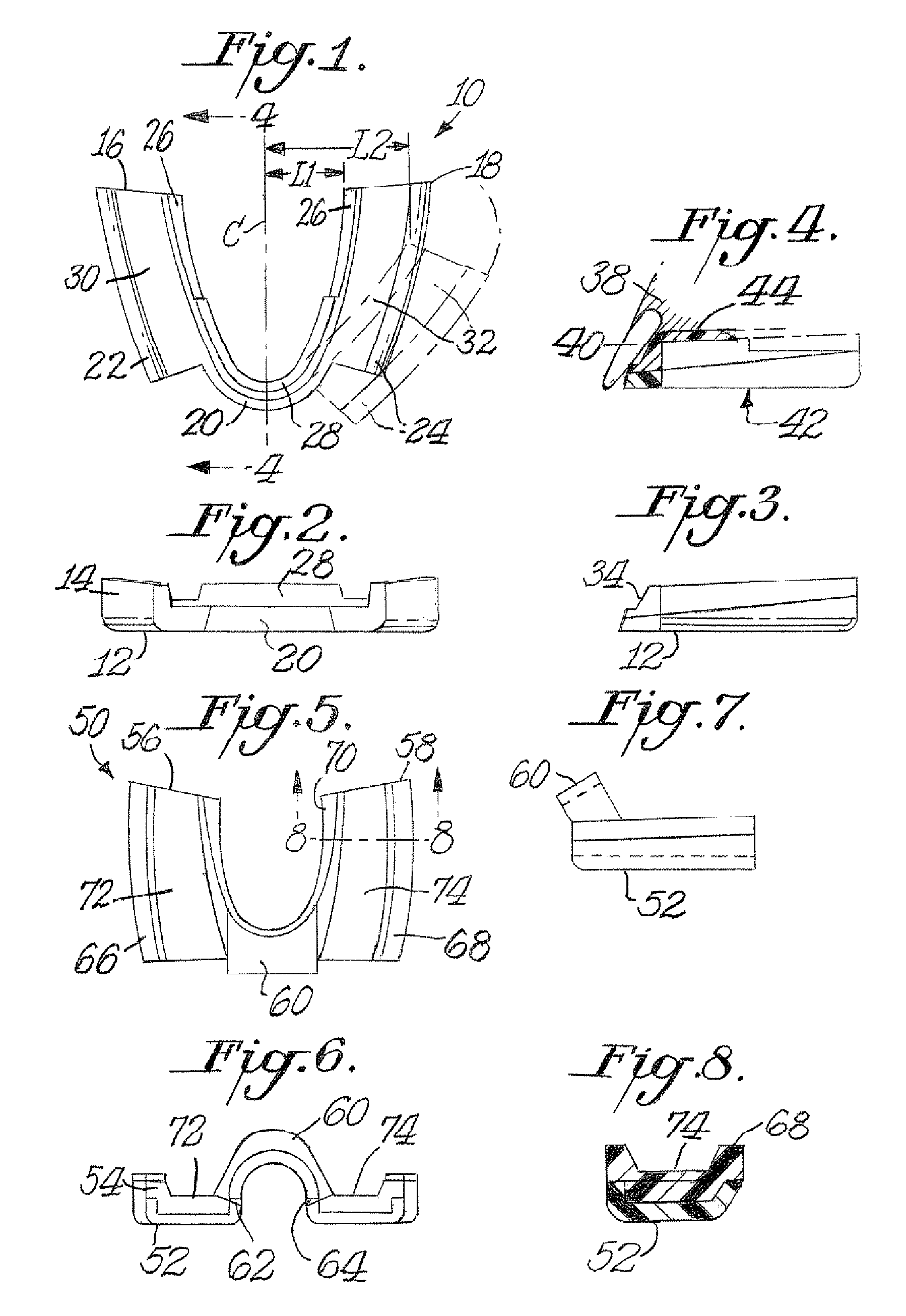
[0068]Referring first to FIGS. 1-3, a preform 10 for an interocclusal appliance 42 is shown. The preform 10 has a base 12 or bite plate with a top surface and a bottom surface. An impression material 14 is bonded or adhered onto the top surface of the base 12. One preferred bonding is by molding the impression material over the base. The base 12 may be formed by injection molding a thermoplastic resin into a base mold cavity, and this base 12 is then placed into an occlusal appliance mold cavity. The impression material 14 may be injected into the occlusal appliance mold cavity over the base 12. The mold bond between the base 12 and the impression material 14 (which later is transformed into the maxillary encasement) is required to withstand the lateral and compressive stresses encountered during bruxing or clenching at oral cavity temperatures.

[0069]The base 12 is in the form of a maxillary dental arch, having an end portion 16 at one terminus of said arch and another end portion 1...

second embodiment

[0085]Referring next to FIGS. 5 to 8, the invention comprises a preform 50 having a base 52 or bite plate with a top surface and a bottom surface. An impression material 54 is adhered or bonded onto the top surface of the base 52, such as by co-molding. The base 52 has two end portions 56, 58 that are joined by an arch 60 formed between the two end portions 56, 58. Arch 60 curves concavely such that each bottom tip of said arch meets an end portion the bottom surfaces (or occlusal faces) of the end portions 56, 58 of the base are generally planar. The buccal sidewalls of the end portions of the base 12 may slope downwardly slightly from the rear of the preform 50 toward the front of the preform as shown in FIG. 7.

[0086]By virtue of flexibility of the arch 60 material, the preform 50 may be flexed from a first position where end portions 56, 58 are spaced apart a first distance to a second position where end portions 56, 58 are spaced apart a second distance, where the second distanc...

third embodiment

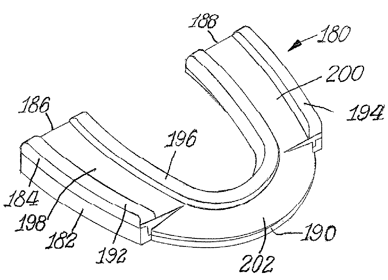
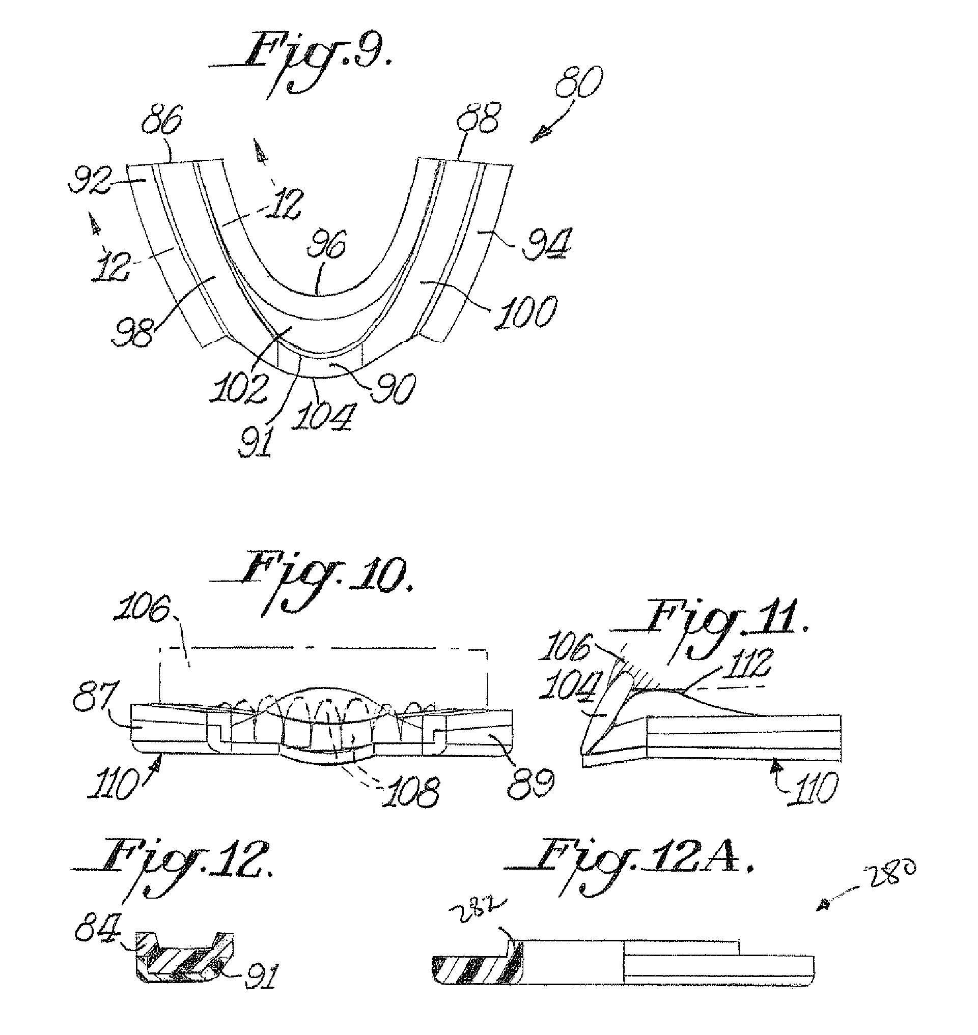
[0089]FIGS. 9 to 12 show a preform 80 and an interocclusal appliance 110 for the invention (appliance 110 shown in FIG. 11). The preform 80 has a base 82 and impression material 84 molded to a top surface of such base 82. The base 82 is in the shape of a maxillary dental arch, having end portions 86, 88 and a central portion 90 between such end portions 86, 88. The end portions 86, 88 have upstanding side walls 87, 89 and an upstanding lingual wail 91 that extends along the dental arch along the end portions 86, 88 and the central portion 90. The central portion 90 of the base 82 has only the upstanding lingual wall 91, and does not have an upstanding labial or front wall.

[0090]The impression material 84 generally covers the top surface of the base 82. The impression material 84 is formed to have a first outer upstanding ridge 92 and a second outer upstanding ridge 94, and an inner upstanding ridge 96. Optionally, a step (not shown) may be formed in the inner upstanding ridge 96 suc...


PUM

PropertyMeasurementUnit
distanceaaaaaaaaaa
thicknessaaaaaaaaaa
temperatureaaaaaaaaaa

Abstract

An interocclusal appliance is formed from a single polymer material composition as one unitary piece or from multiple polymer material compositions as a two-piece preform. The two-piece preform includes a base material and an impression material that has a softening point lower than the base material. Teeth are received into the heat-softened impression material, so as to contour the impression material. A portion of the impression material also may contour to a portion of the user's palate. In certain embodiments, substantially no polymeric material contacts the front surfaces of the front teeth, leading to greater comfort and better air flow between front teeth. In still another embodiment, the appliance fits over front teeth only and no polymeric material contacts the maxillary molars.

Description

BACKGROUND OF THE INVENTION[0001]1. Field of the Invention[0002]This invention relates to interocclusal appliances worn in the mouth to prevent tooth structure loss resulting from subconscious parafunctional mandibular habits known as bruxism or clenching.[0003]2. Description of the Prior Art[0004]Bruxism has been found to be a major factor in occlusal tooth surface wear, and may be a significant potential risk factor for dental implant failure. Interocclusal appliances, such as mouth guards or nightguards, have been recognized as beneficial to alleviate the adverse effects of bruxism and clenching.[0005]Prior interocclusal appliances include those that are fitted by a dental professional and those that are self-fitted. Professionally fitted interocclusal appliances are molded of relatively hard acrylic resin from casts of the patient's mouth taken from a dental impression. This procedure requires multiple visits to the dental professional's office, and thus is time-consuming and ex...

Claims


Application Information

Patent Timeline
Patent Type & Authority Patents(United States)
IPC IPC(8): A61C7/08A61C5/14
CPCA61F5/566Y10T156/10A61F2005/563B29K2009/00A61F5/56
Inventor LESNIAK, FRANK
Owner HAYLOFT ENTERPRISES INC
Why Eureka
Try Eureka