Toilet bolt cover

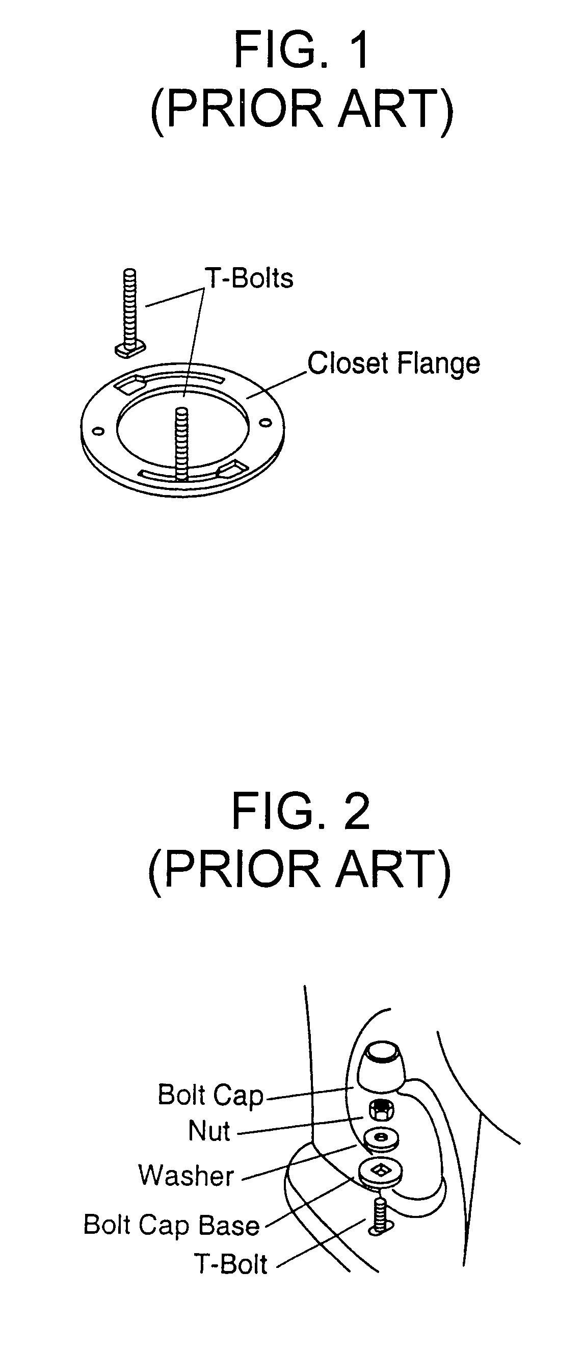
a technology for toilet bolts and covers, which is applied in the field of toilet bolt covers, can solve the problems of time-consuming and difficult procedure of cutting off the end of the bolt, the unsightly appearance of exposed nuts and bolts, and the insufficient depth of the conventional bolt cap to fit over such a long bolt. achieve the effect of convenient installation and easy removal

Active Publication Date: 2010-02-09
CONWAY DOUGLAS E +1
View PDF18 Cites 37 Cited by
  • Summary
  • Abstract
  • Description
  • Claims
  • Application Information

AI Technical Summary

Benefits of technology

[0008]The general object of this invention is to provide an improved toilet bolt cover. More particular objects are to provide a toilet bolt cover that completely and securely seals the end of the toilet bolt, the nut, and the washer, that accommodates toilet bolts of varying lengths, and that is easily installed and easily removed.

Problems solved by technology

Exposed nuts and bolts are unsightly so they are typically hidden with a porcelain or plastic cover.
Conventional bolt caps are not deep enough to fit over such a long bolt.
Cutting off the end of the bolt is a time-consuming and difficult procedure.
Furthermore, if a different toilet with a thicker base is installed later, or if a thicker floor covering is added later, the cut-off bolt may not be long enough to attach a nut.
These bolt caps do not contain a base and therefore do not form an effective seal around the bolt, nut, and washer.
Furthermore, there is no means for preventing the base from rotating.
Accordingly, removing the cap may be very difficult because the base tends to rotate with the cap.

Method used


Image

  • Toilet bolt cover
  • Toilet bolt cover
  • Toilet bolt cover

Examples


first embodiment

1. First Embodiment

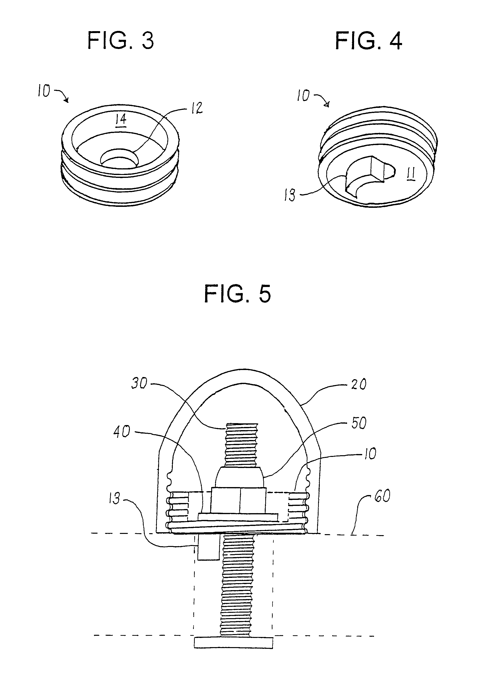
[0027]This invention is best understood by reference to the drawings. A first embodiment of the toilet bolt cover of this invention is shown in FIGS. 3 to 5. The cover comprises a base 10 and a cap 20. The cover hides from view the end of a toilet bolt 30, a washer 40, and a nut 50 that are used to mount a toilet 60. The base of the toilet is shown in phantom lines in FIG. 5.

[0028]The base of the cover has a disc portion 11 that rests on the upper surface of the toilet base. The disc portion is preferably round, flat, and as thin as possible to enable toilet bolts having the shortest length possible to be used. The ability to accommodate relatively short bolts is especially useful in retrofit applications where the bolt has previously been shortened. The disc portion generally has a thickness of about 1 to 10 mm, preferably about 2 to 5 mm. The disc portion has a centrally located hole 12 to accommodate the toilet bolt. The diameter of the hole is generally about ...

second embodiment

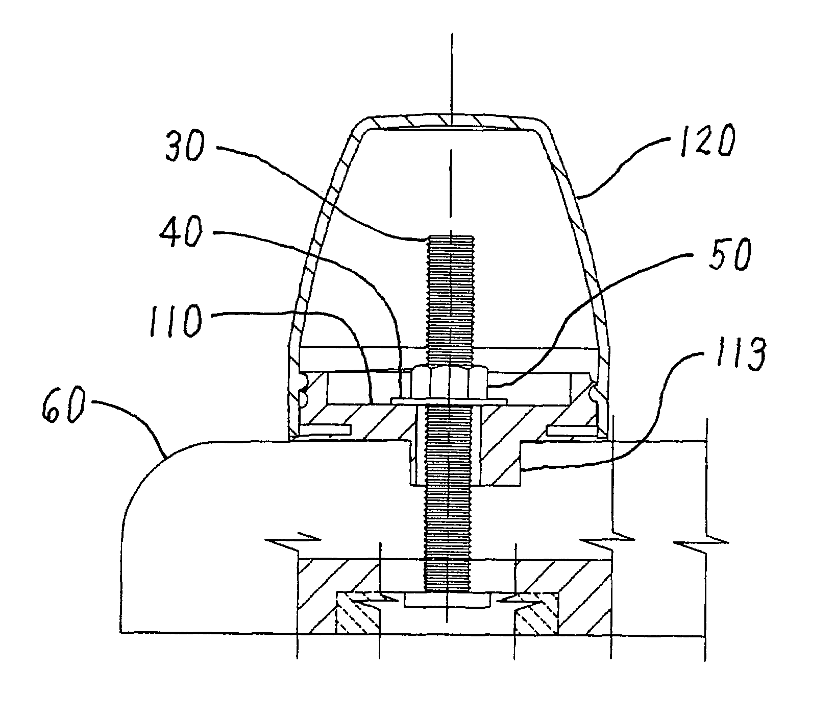
2. Second Embodiment

[0032]A second embodiment of the toilet bolt cover is shown in FIGS. 6 to 16. The base 110 of the cover of this embodiment differs from the base of the first embodiment in two respects. First, the descending member 113 includes an integral sleeve that completely surrounds the hole for the bolt. The integral sleeve provides additional strength to the descending member and reduces the risk of breakage. Second, the base contains a flexible annular seal 115. The seal flattens against the top of the toilet base as the nut on the bolt is tightened. The purpose of the seal is to conform to, the top of the toilet base even if the top is not perfectly flat. The seal prevents liquids and materials from entering the hole in the base and thereby reduces odor and the growth of undesirable microorganisms. The diameter of the seal may be less than, equal to, or greater than the diameter of the cap. If the diameter of the seal is less than the diameter of the cap, the cap sits d...


PUM


Abstract

A toilet bolt cover hides the portion of a toilet bolt extending upwardly through a mounting hole in the toilet base along with a washer and a nut threaded upon the bolt. The cover includes a base and a cap. The base has a wall with external threads and the cap has internal threads. The base of the cover has a descending member that extends downwardly into the mounting hole in the toilet base to limit rotation of the base of the cover.

Description

CROSS-REFERENCE TO RELATED APPLICATION[0001]This application claims the benefit of U.S. Provisional Application Ser. No. 60 / 772,606, Feb. 10, 2006.FIELD OF THE INVENTION[0002]This invention relates to toilets. More particularly, this invention relates to covers for toilet bolts.BACKGROUND OF THE INVENTION[0003]A toilet is a standard fixture of indoor plumbing. A toilet is connected to a source of water and is mounted over a floor drain. As shown in FIGS. 1 and 2, a toilet is secured in position on the floor with two toilet bolts (sometimes known as T-bolts because of the shape of their heads) that extend upwardly from a closet flange at the mouth of the drain. The toilet contains oblong holes in its base that are placed over the bolts. The term “oblong” is used herein to refer to an elongated shape in which one dimension is greater than a perpendicular dimension. Washers and nuts are then inserted onto the bolts and tightened.[0004]Exposed nuts and bolts are unsightly so they are ty...

Claims


Application Information

Patent Timeline
Patent Type & Authority Patents(United States)
IPC IPC(8): F16B37/14A47G3/00
CPCA47G3/00
Inventor CONWAY, DOUGLAS E.BODINE, RUSSELL L.
Owner CONWAY DOUGLAS E
Why Eureka
Try Eureka