Tag privacy protection method, tag device, backend apparatus, updater, update solicitor and record medium carrying such programs in storage

a privacy protection and tag technology, applied in the field of tag privacy protection methods, backend apparatus, updaters, update solicitors and record media carrying such programs in storage, can solve the problem that the information of articles under control may leak through eavesdropped tag id information

Active Publication Date: 2010-02-09
NIPPON TELEGRAPH & TELEPHONE CORP
View PDF40 Cites 17 Cited by
  • Summary
  • Abstract
  • Description
  • Claims
  • Application Information

AI Technical Summary

Benefits of technology

[0023]As mentioned above, according to the present invention, a third party cannot know the correspondence between a tag device and a history of communications, and accordingly, a tracing of a distribution process of the tag device by a third party can be prevented.

Problems solved by technology

However, in the basic automatic tag identification system, anyone who is in possession of a reader can read tag ID information, and accordingly, there has been a risk that information of articles under control may leak through eavesdropped tag ID information.

Method used


Image

  • Tag privacy protection method, tag device, backend apparatus, updater, update solicitor and record medium carrying such programs in storage
  • Tag privacy protection method, tag device, backend apparatus, updater, update solicitor and record medium carrying such programs in storage
  • Tag privacy protection method, tag device, backend apparatus, updater, update solicitor and record medium carrying such programs in storage

Examples


embodiment 1

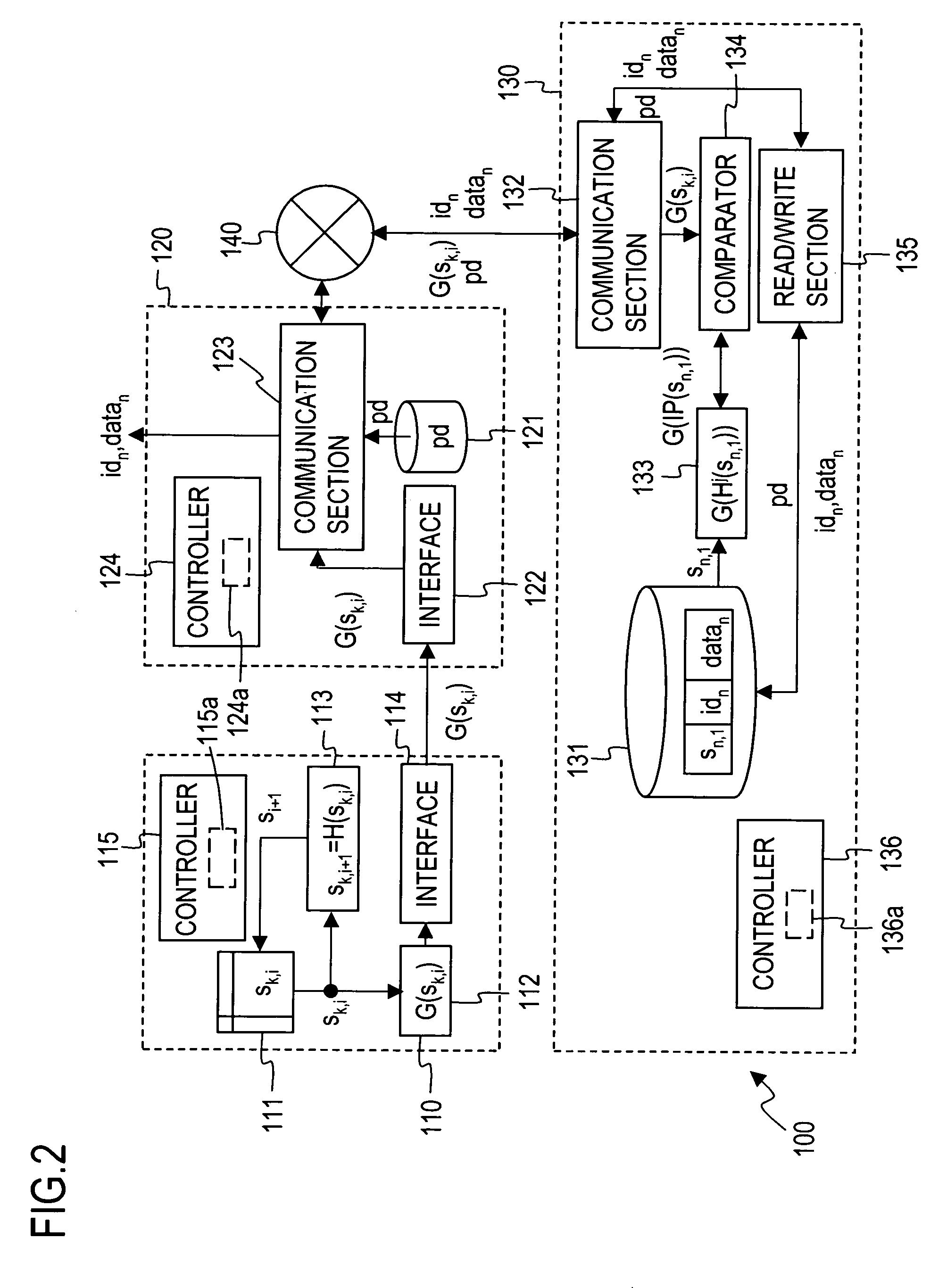
[0119]FIG. 2 illustrates an overall arrangement of an automatic tag identification system 100 in an embodiment 1 according to the first mode, and FIG. 3 is a flow chart for describing processing in the embodiment 1.

[0120]Referring to these Figures, the functional arrangement and a method of processing in the embodiment 1 will be described below.

[0121]

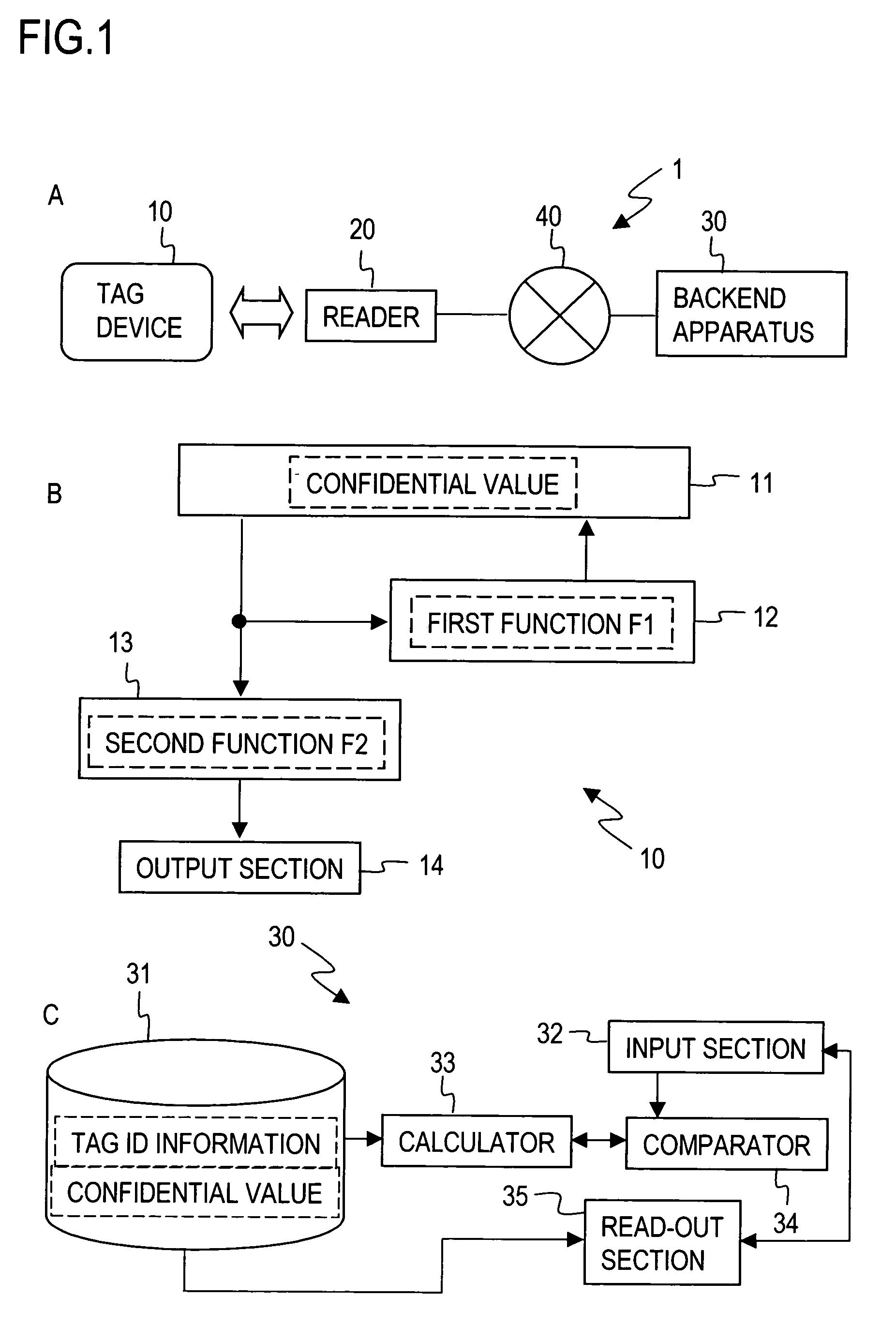
[0122]As illustrated in FIG. 2, the automatic tag identification system 100 of the embodiment 1 comprises a tag device 110, a reader 120 and a backend apparatus 130 which is connected to the reader 120 through a network 140 so as to be capable of communication therewith. While in FIG. 2, only one tag device 110 is shown for purpose for simplifying the description, it should be noted that more tag devices exist in actuality. In addition, while one reader 120 and one backend device 130 are shown in FIG. 2, more readers 120 and backend apparatus 130 may be used to construct the present system.

[0123]

[0124]The tag 110 device in this example ...

embodiment 2

[0162]An embodiment 2 is a modification of the embodiment 1, and differs from the embodiment 1 only in respect of the fact that the tag device additionally carries tag ID information idk (equivalent to “first proper value wk”) to update the confidential value sk, i according to sk, i+1=H(sk, i|idk). In the description to follow, only distinctions over the embodiment 1 will be described.

[0163]FIG. 4 illustrates an overall arrangement of an automatic tag identification system 200 according to the embodiment 2. It is to be noted that in this Figure, parts which are common with the embodiment 1 are designated by common characters as used in the embodiment 1. Referring to this Figure, the functional arrangement and a processing method of the embodiment 2 will be described below.

[0164]

[0165]A distinction over the embodiment 1 lies in the fact that tag ID information idk and a corresponding confidential value sk, i are stored in a confidential value memory 211 of a tag device 210. A backen...

embodiment 3

[0176]This represents a modification of the embodiment 1, and the difference with respect to the embodiment 1 exists only in recording a calculated value G(Hj(sn, 1)) (j=0, . . . , jmax) which is previously calculated in the backend apparatus. Only a distinction over the embodiment 1 will be described below.

[0177]FIG. 5 is an illustration of an overall arrangement of an automatic tag identification system 300 according to an embodiment 3. In this Figure, parts which are common to the embodiment 1 are designated by common characters as used in the embodiment 1. FIG. 6 is a flow chart for describing processings by a backend apparatus 330 in the embodiment 3. A functional arrangement and the processing method of the embodiment 3 will be described below with reference to these Figures.

[0178]

[0179]Storing a result of calculation G(Hj(sn, 1)) (j=0, . . . , jmax) which is previously calculated by the hash calculator 133 in a database memory 331 of the backend apparatus 330 in a manner rela...


PUM


Abstract

A tag device causes a second calculator to read a confidential value from a confidential value memory and to apply a second function F2 which disturbs a relationship between elements of a definition domain and a mapping thereof to generate tag output information. The tag device delivers the tag output information to a backend apparatus. Subsequently, a first calculator reads out at least part of elements of the confidential value from the confidential value memory, and applies a first function F1, an inverse image of which is difficult to obtain, and a result of such calculation is used to update a confidential value in the confidential value memory by overwriting.

Description

TECHNICAL FIELD[0001]The present invention relates to a tag technology incorporating information security technology, in particular, to a method of protecting tag privacy against acquisition of a user privacy information from information delivered from a tag device, a tag device, a backend apparatus, an updater, an update solicitor, programs therefor and a record medium carrying such programs in storage.BACKGROUND ART[0002]Recently an automatic tag identification system such as RFID (Radio Frequency Identification) is increasingly introduced. The system comprises an information record medium of a small size referred to as “tag device”, a reading machine referred to as “reader” and a database server referred to as “backend apparatus”, and is utilized in controlling the distribution of articles. A summary of this technology will be given below.[0003][Processing by Tag Device][0004]In a basic automatic tag identification system, each tag device has a tag ID information which is inheren...

Claims


Application Information

Patent Timeline
Patent Type & Authority Patents(United States)
IPC IPC(8): G06F21/00H04L9/32G06F12/14G06F21/62G06F21/64G06K17/00G06K19/073
CPCG06F21/606G06F21/62G06F21/6245G06F21/73G06Q10/08G06Q20/40975G07F7/1008H04L9/3073H04L9/3236G06Q20/341H04L2209/805H04L2209/20G06K19/073H04L9/32G06F12/14G06K17/00
Inventor OHKUBO, MIYAKOSUZUKI, KOUTAROUKINOSHITA, SHINGO
Owner NIPPON TELEGRAPH & TELEPHONE CORP
Why Eureka
Try Eureka