Automatic calibration of a laser processing system using an integrated telecentric optical detector with limited degrees of freedom

a laser processing system and automatic calibration technology, applied in additive manufacturing processes, program control, instruments, etc., can solve the problems of laser processing system thermally driven fluctuations, laser processing system exposure to progressive loss of accuracy, etc., and achieve the effect of simplifying the formation of replicas

Pending Publication Date: 2021-10-21
RAYLASE GMBH
View PDF0 Cites 0 Cited by
  • Summary
  • Abstract
  • Description
  • Claims
  • Application Information

AI Technical Summary

Benefits of technology

The patent describes a method for laser processing materials using reference marks generated by a laser device. These reference marks are detected by an optical detector within the laser processing system, which allows for faster calibration and reduced interruption of operation compared to previous solutions. The technical effect of this method is improved accuracy and efficiency in laser processing.

Problems solved by technology

During operation, any laser processing system is subject to thermally driven fluctuations caused, for instance, by heat produced by the laser devices or by the electronic workpieces of the system.
These fluctuations can affect the accuracy of the laser devices, for example in the form of offset drifts and gain drifts.
Due to the aforesaid fluctuations and the possibly resulting drifts, and in spite of an appropriate initial calibration of the system for initially adjusting the settings of the laser devices, any laser processing system may be exposed to a progressive loss of accuracy, especially when a plurality of laser devices are configured for operating in parallel.
However, such traditional calibration processes usually involve several time-consuming iterations and often require the intervention of a human operator, for example for providing and removing a marking paper or a reference plate and for preparing and carrying out the aforesaid measurements using the software tool and the measuring equipment.

Method used


Image

  • Automatic calibration of a laser processing system using an integrated telecentric optical detector with limited degrees of freedom
  • Automatic calibration of a laser processing system using an integrated telecentric optical detector with limited degrees of freedom
  • Automatic calibration of a laser processing system using an integrated telecentric optical detector with limited degrees of freedom

Examples


Embodiment Construction

[0120]For the purposes of promoting an understanding of the principles of the invention, reference will now be made to preferred embodiments illustrated in the drawings, and specific language will be used to describe the same. It will nevertheless be understood that no limitation of the scope of the invention is thereby intended, and that such alterations and further modifications of the illustrated embodiments as well as further applications of the principles of the invention illustrated herein are contemplated as would normally occur now or in the future to one skilled in the art to which the invention relates.

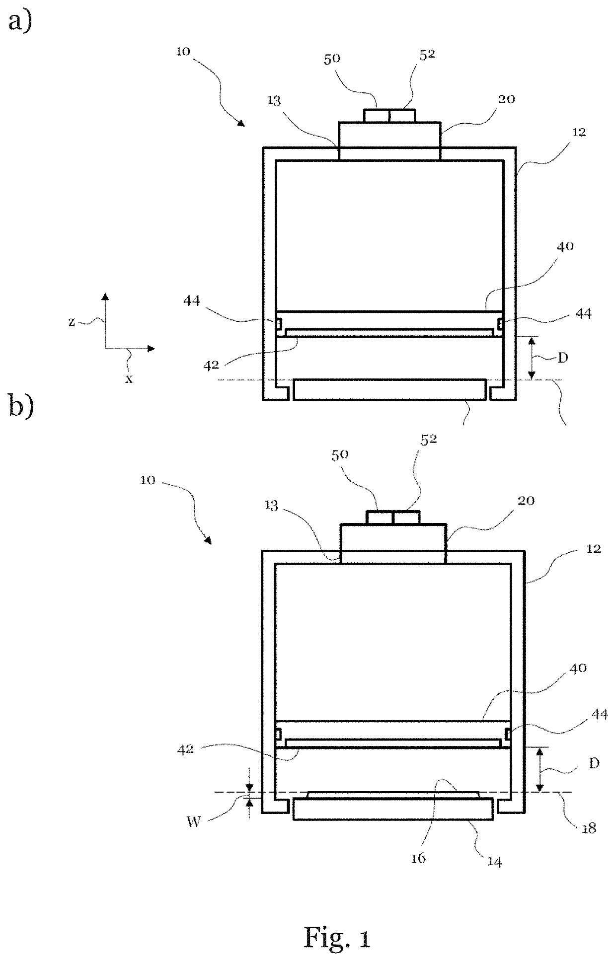
[0121]FIG. 1 shows a laser processing system according to an embodiment of the invention. The laser processing system of the embodiment shown in FIG. 1 is an additive manufacturing system 10. The system 10 comprises a frame structure 12 and a work base 14 that is configured for supporting a work material. In the embodiment shown, the frame structure 12 is formed as a housing...


PUM

PropertyMeasurementUnit
Angleaaaaaaaaaa
Speedaaaaaaaaaa
Speedaaaaaaaaaa

Abstract

The present invention relates to a laser processing system (10) comprising a frame structure (12); a work base (14) for supporting a work material (16), wherein the work base (14) defines a work field (28) in a work plane (18), wherein the work plane (18) is parallel to the work base (14); at least one laser device (20) for projecting work light on the work plane (18) and / or on the work material (16), when the work material (16) is disposed on the work base (14), wherein the at least one laser device (20) is attached to the frame structure (12); wherein each laser device (20) is configured for generating one or more reference marks (24) on the work material (16) and / or on the work plane (18) within the corresponding laser field (30), wherein the laser field (30) corresponds to at least a part of the work field (28); an optical detector (40) for scanning the work field (28) for detecting at least a part of the one or more reference marks (24) generated by each laser device (20), wherein the optical detector (40) is movable with respect to the frame structure (12) with not more than two, preferably not more than one, degree of freedom; and a control unit (50) functionally connected to the optical detector (40) and the at least one laser device (20), wherein the control unit (50) is configured for calibrating the at least one laser device (20) based on the reference marks (24) detected by the optical detector (40). The invention further refers to a related method of calibrating one or more laser devices of a laser processing system.

Description

FIELD OF THE INVENTION[0001]The present invention is in the field of additive manufacturing and relates to a laser processing system and a method for calibrating a laser processing system.BACKGROUND OF THE INVENTION[0002]Additive manufacturing processes are an example of laser processing processes. In additive manufacturing processes, a work material is added and laser processed layer by layer to manufacture a target workpiece out of the work material. Additive manufacturing is gaining more and more importance in industrial production compared to classical subtractive manufacturing processes such as milling, drilling and turning, in which material is removed to produce a workpiece. Layer-based construction, which is characteristic of additive manufacturing processes, enables the production of highly complex geometric structures with a high degree of design space that subtractive processes cannot achieve.[0003]The increase in the industrial significance of additive manufacturing proc...

Claims


Application Information

Patent Timeline
IPC IPC(8): B23K26/03B23K26/04B22F10/20B22F10/30B23K26/70B29C64/393
CPCB23K26/032B23K26/04B22F10/20B29C64/153B23K26/707B29C64/393B22F10/30G05B19/401G05B2219/45041B33Y50/02B23K26/60B23K26/702Y02P10/25B22F10/28B22F10/31B22F12/38B22F10/366B22F12/90B22F12/45
Inventor LEHMANN, WOLFGANG
Owner RAYLASE GMBH
Why Eureka
Try Eureka