Method for making segmented composite panel with false joints

a composite panel and segmented technology, applied in the field of composite panels, can solve the problems of high installation cost of panels, high insulation cost of panels, and cumbersome process, and achieve the effect of simplifying the formation of false joints

Active Publication Date: 2010-03-16
NUCOR INSULATED PANEL GRP LLC
View PDF8 Cites 29 Cited by
  • Summary
  • Abstract
  • Description
  • Claims
  • Application Information

AI Technical Summary

Benefits of technology

[0008]The present invention simplifies the formation of false joints in larger composite architectural panels using a continuous facer element along with a continuous liner element bonded to a core material. The false joints can be formed at any position along the length of the panel, and allows various aesthetic designs to be achieved through strategic attachment of the panels to the building frame. One such design that can be achieved is a masonry brick design where the false joints are placed such that the panels have a staggered appearance. Also by staggering the panels a running bond appearance is achieved. The panels may be flat or have a textured surface, and by embossing or chamfering the flat area of the panel, a stone effect can be achieved. Also, this process allows a greater number of false joints and a shorter length of facer sheet between the false joints as compared to the prior art of individual facer sheets between the false joints.
[0016]It is an object of the present invention to reduce manufacturing and / or installation costs associated with composite panels having false joints.
[0017]It is a further object of the present invention to provide a composite panel having false joints with improved thermal efficiency.
[0019]It is still a further object of the present invention to increase the strength of composite panels having false joints.

Problems solved by technology

All of the above tends to represent a rather cumbersome and costly process.
The insulation costs of the panels is a function of their size in length and width.
When short panels are required, the per unit installation costs of the panels is quite high.
Forming larger panels having the separate facer elements forming the false joints became quite cumbersome and costly in the plant.
Quality issues also arose due to panel length variations and the use of separate facer elements to form the false joints.

Method used


Image

  • Method for making segmented composite panel with false joints
  • Method for making segmented composite panel with false joints
  • Method for making segmented composite panel with false joints

Examples


Embodiment Construction

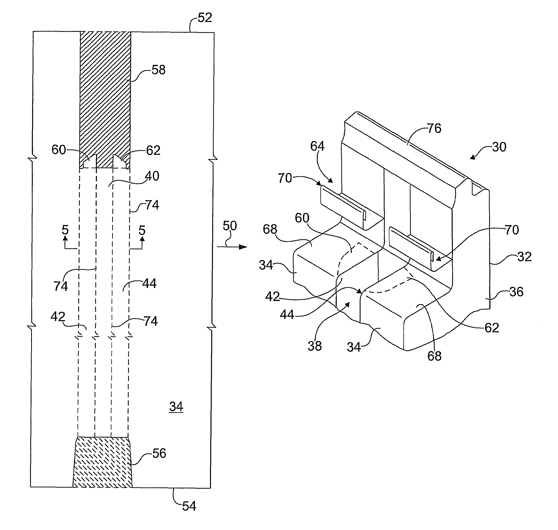
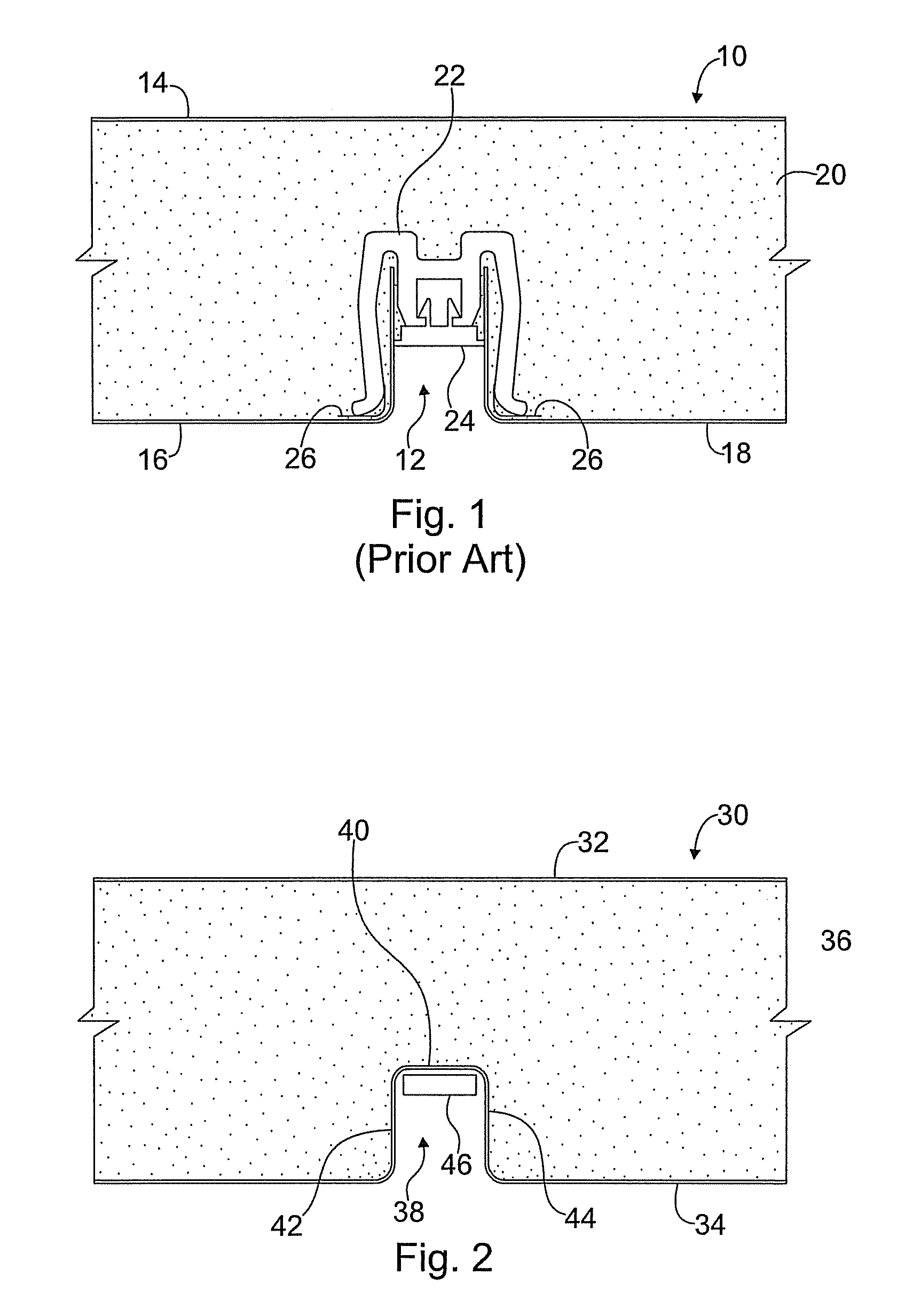
[0033]FIG. 2 illustrates a partial cross-sectional view of a composite building panel, shown generally at 30, manufactured in accordance with the present invention, at one of its false joints. The building panel 30 includes a liner element 32, a facer element 34, and a core material 36 bonded to the liner 32 and facer 34 elements and filling the interior space of the building panel 30. The liner 32 and facer 34 elements may also be referred to herein as sheets. Typically, the core material 36 is an insulating, structural foam core made from a foam or polymer (e.g., polyurethane). However, other core materials may be used without departing from the spirit and scope of the present invention.

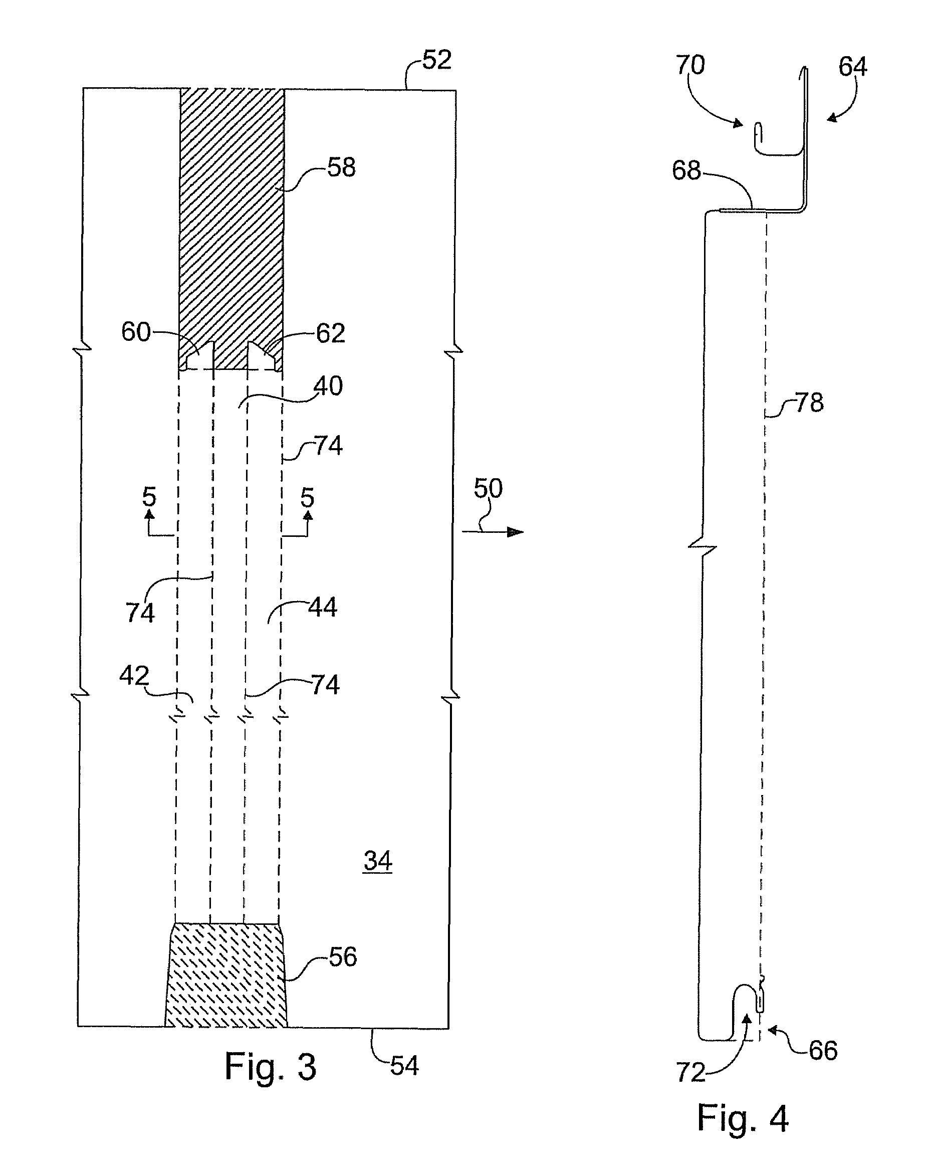
[0034]As shown in FIG. 2, the building panel 30 includes a false joint 38 formed therein at predefined positions along the length of the facer element 34. Typically, the liner element 32 defines the interior surface of the building panel 30, while the facer element 34 is the exterior surface of the...


PUM

PropertyMeasurementUnit
areaaaaaaaaaaa
lengthaaaaaaaaaa
adhesiveaaaaaaaaaa

Abstract

A method of forming a building panel is provided, with the building panel including facer and liner sheets surrounding a foam core. The method includes the steps of pre-notching the facer sheet at each false joint, roll forming the side joints of the facer sheet, bending the facer sheet, via a press operation, at the pre-notched area to form the false joint, such that the facer sheet is a continuous sheet across the false joint, and bonding the facer sheet having the false joint and the liner sheet to the foam core to form the building panel.

Description

FIELD OF THE INVENTION[0001]The present invention is directed toward composite architectural panels and, more particularly, towards composite architectural panels with false joints and methods of making the same.BACKGROUND OF THE INVENTION[0002]Composite architectural wall panels have typically been manufactured in multi-step processes which often involve both sheet manufacturers and panel fabricators. Initially, a composite sheet is manufactured by laminating metal skins to a plastic or foam core. An example of such a composite sheet is the “ALUCOBOND” material produced by Alusuisse Group, Ltd., Zurich, Switzerland. Then, the sheets are typically shipped to a fabricator where they are cut to size and routed so as to return the edges around the perimeter. Extrusions are typically fabricated and applied to the panel perimeter to create panel joinery. Also, stiffeners are typically applied in the field to the major flattened portion of the panel to reduce bowing of the panel under a l...

Claims


Application Information

Patent Timeline
Patent Type & Authority Patents(United States)
IPC IPC(8): B32B38/04B29C65/56E04B2/42B31F1/00
CPCB32B38/00E04C2/292B32B2607/00Y10T156/1066Y10T156/1002Y10T156/1007Y10T156/1056Y10T156/1052Y10T156/1062
Inventor THOMPSON, ROBBIEVEAZEY, STEVENEDWARDS, CHARLESATCHLEY, RUSSELL
Owner NUCOR INSULATED PANEL GRP LLC
Why Eureka
Try Eureka