Sliding panel

a sliding panel and panel technology, applied in the field of sliding panels, can solve the problems of reducing reducing requiring more material and money, so as to reduce the amount of material used for producing the rail, simplify the rail set formation, and reduce the number of channels of the rail

Active Publication Date: 2012-10-30
CHU
View PDF69 Cites 36 Cited by
  • Summary
  • Abstract
  • Description
  • Claims
  • Application Information

AI Technical Summary

Benefits of technology

[0005]Therefore, in a set of sliding panels, the number of channels of the rails is decreased and the amount of material used for producing the rail is reduced.
[0006]It is the other object of the present invention to provide a sliding panel that includes a channel on each rail and a rail set formed by at least one rail (such as one, two or three rails) arranged in parallel so as to meet the requirements of simplified rail set formation, precision, and easy assembling.

Problems solved by technology

Once the rail is designed into an extendable rail consisting of an inner rail and an outer rail, it is difficult to form the extrusion of the rails precisely, so that the rails can't be telescoped smoothly.
Furthermore, because of the bulky sizes of the rails, they need more material and cost more money.
But another problem is encountered, since a sliding panel with 3 to 6 rails needs a lot of material and cost a lot of money.
Furthermore, it is difficult to combine 3 to 6 rails and install them together.

Method used


Image

  • Sliding panel
  • Sliding panel
  • Sliding panel

Examples


embodiment 1

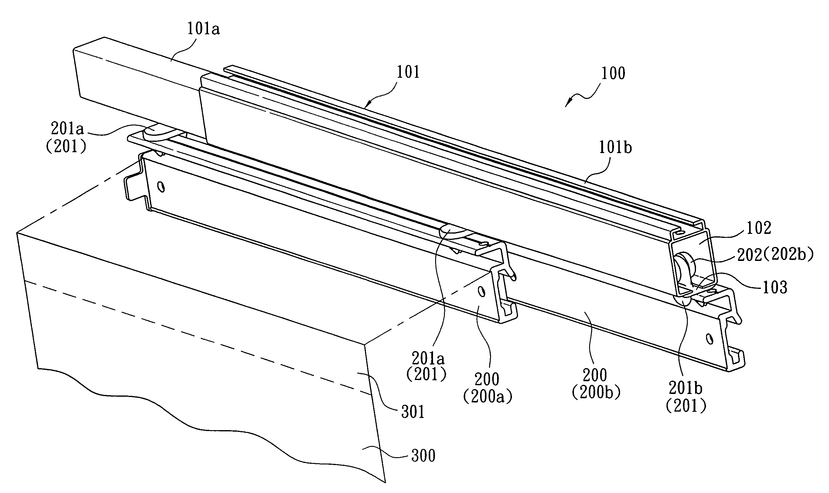
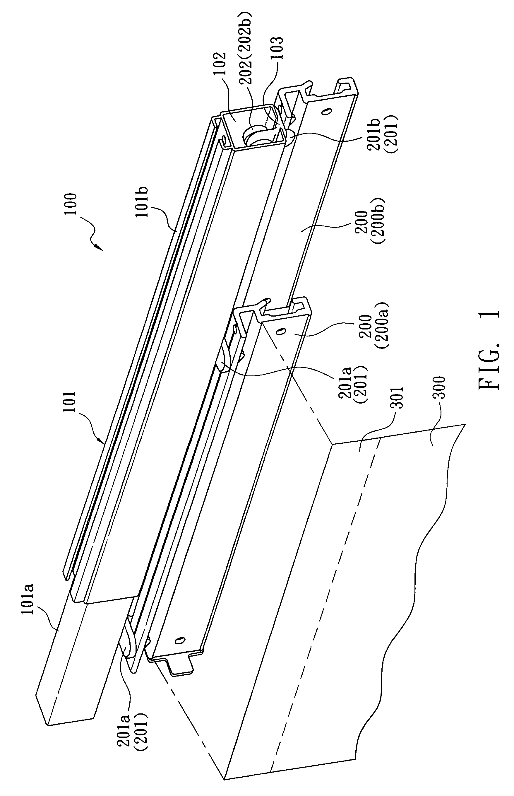
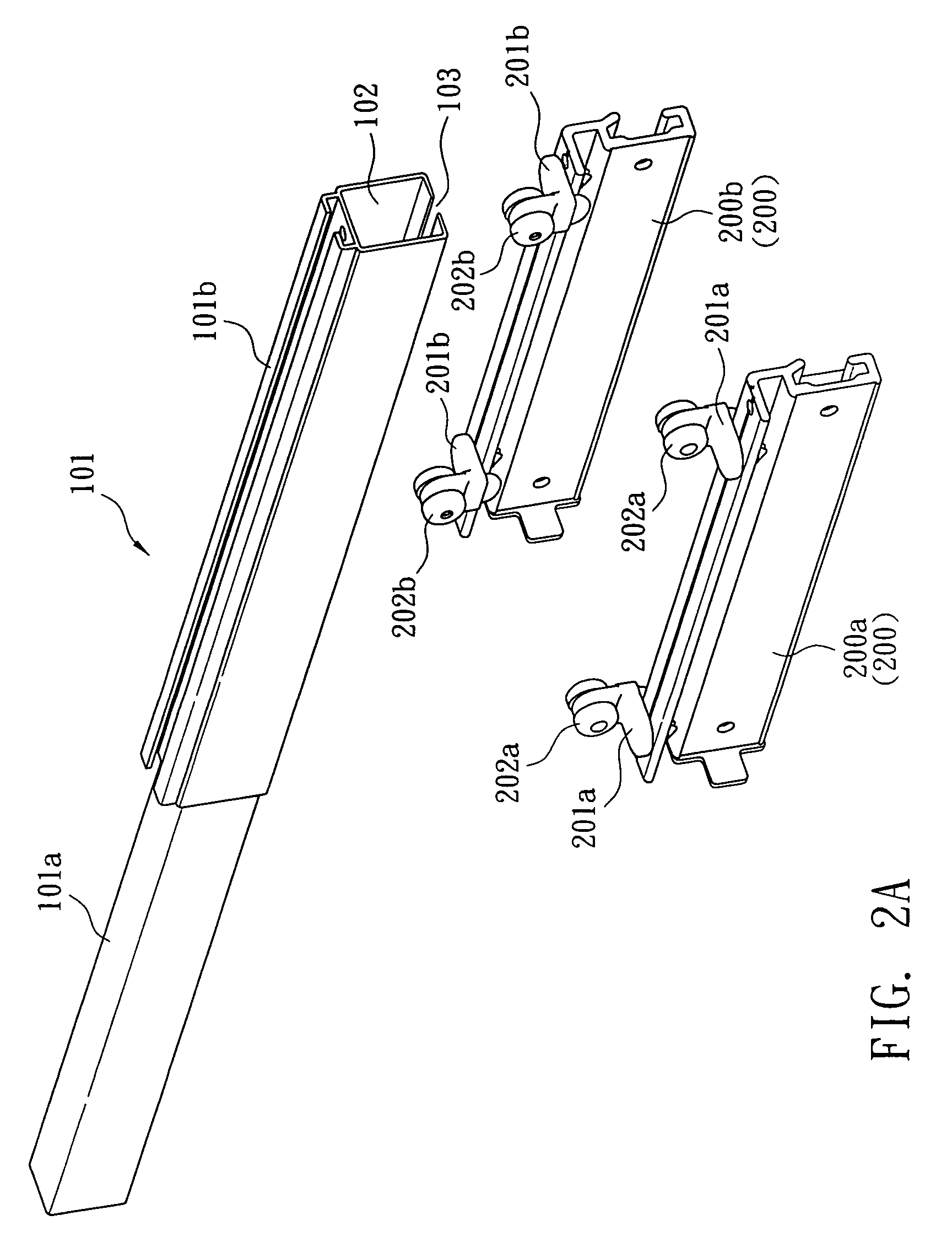
[0035]Referring to FIG. 1 to FIG. 5, where only a single channel 102 is disposed on a rail 101 while two carrier tracks 200 are arranged in parallel under the single channel 102. The rail set 100 of this embodiment is composed of a rail 101.

[0036]The two connectors 201a, 201b are disposed in opposite directions on two carrier tracks 200a, 200b of the two adjacent panels 300. The right end of the connector 201a of the left carrier track 200a inserts through the channel opening 103 of the rail 101 and connects to one runner 202a while left end of the connector 201b of the right carrier track 200b inserts through the channel opening 103 of the rail 101 and connects to one runner 202b. Thus, the right connector 201b and left connector 201a are respectively located under left and right sides under the channel opening 103 of the channel 102. Furthermore, left and right carrier tracks 200a, 200b respectively connecting with the left and right connectors 201a, 201b are disposed in parallel ...

embodiment 2

[0038]Referring to FIG. 6 to FIG. 10A, 10B, where four carrier tracks 200 are disposed in parallel under two channels 102 of the two rails 101. The rail set 100 of this embodiment includes two rails 101. This embodiment is formed by two sets of the embodiment 1. The runners 202a, 202b, of the two carrier tracks 200a, 200b are simultaneously mounted and slide inside a channel 102 of each of the two rails 101. Thus the two adjacent carrier tracks 200a, 200b slide under each of the channels 102 in parallel.

[0039]Moreover, by the driving mechanism and the positioning mechanism disposed on the sliding panel, two sets of the two carrier tracks 200a, 200b, for a total of four carrier tracks—200a, 200b, 200a, 200b move in parallel under the rail set 100 composed of two rails 101 so as to be extended or retracted, overlapping with one another.

embodiment 3

[0040]Referring to FIG. 11A to FIG. 16, where only one channel 102 is mounted on a rail 101 and there are three carrier tracks 200 arranged and sliding in parallel under the channel 102. The rail set 100 of this embodiment consists of one rail 101. The difference between this embodiment and the embodiment 1 is that a set of two adjacent carrier tracks 200a, 200b and the panels 300 thereof is replaced by a set of three adjacent carrier tracks 200a, 200c, 200b and the panels 300 thereof. The connectors 201a, 201c, 201b respectively disposed on the three carrier tracks 200a, 200c, 200b of the three adjacent panels 300 are arranged in opposite directions or at intervals. The distance between the left and right carrier tracks 200a, 200b is enlarged so as to add a middle carrier track 200c as well as a panel 300 therein. An alternating connector 201c is arranged between the two connectors 201a, 201b disposed in opposite directions. A middle part of the connector 201c of the middle carrier...


PUM


Abstract

A sliding panel includes multiple connecting / adjacent carrier tracks such as two / three / four carrier tracks while connectors of each carrier track are disposed in opposite directions or at intervals. Thus the multiple connecting / adjacent carrier tracks slide in parallel under the same channel. Moreover, the positions of each connector on top surface of respective carrier track are in alternating arrangement so as to allow runners of multiple connecting / adjacent carrier tracks being mounted inside the same channel simultaneously. The runners of the connecting / adjacent carrier tracks move inside the channel of a rail at the same time and the connecting / adjacent carrier tracks slide in parallel under the same channel. Therefore, the number of channels of the rail is decreased and the amount of material used for producing the rail is reduced. Furthermore, the rail can be designed to have two-step inner and outer rails for adjusting length of the rail. Moreover, each rail is disposed only with one channel and then a plurality of rails such as one / two / three rails are arranged in parallel to form a rail set for easy assembling.

Description

BACKGROUND OF THE INVENTION[0001]The present invention relates to a sliding panel, especially to a sliding panel that uses a single channel on a rail for accommodation of a plurality of carrier tracks simultaneously sliding in parallel.[0002]A sliding panel is one kind of screen and is composed of a rail, a plurality of carrier tracks mounted under the rail, and a plurality of panels attached to the carrier track. Two separating connectors are arranged on the top surface of each carrier track while a runner such as a caster is connected on top of the connector. By inserting the connector upwards through a channel opening on bottom of the rail, the runner slides inside the channel of the rail. Thus each of the carrier tracks and panels thereof slides transversely so as to make the panels extend or retract, overlapping with one another. There is a small overlapping area between the two adjacent panels after being extended so that the multiple panels form a continuous surface to achiev...

Claims


Application Information

Patent Timeline
Patent Type & Authority Patents(United States)
IPC IPC(8): E06B3/12E05D15/06
CPCE06B9/36A47H2001/047A47H2023/025
Inventor CHU, CHEN-HO
Owner CHU
Why Eureka
Try Eureka