Capping device with bearing mechanism having a plurality of bearing members between a drive member and a capper body

a technology of bearing mechanism and capping device, which is applied in the direction of caps, rotating screw stopper insertion, liquid handling, etc., can solve the problems of shaft binding, preventing uniform sliding movement, and cap not being properly positioned on the container. , to achieve the effect of preventing relative rotational movemen

Inactive Publication Date: 2010-02-16
ADCOR INDS
View PDF38 Cites 15 Cited by
  • Summary
  • Abstract
  • Description
  • Claims
  • Application Information

AI Technical Summary

Benefits of technology

[0005]The present invention provides a capping device for fitting caps onto containers by applying an axial force to the caps as they are threaded onto the containers. The capping device includes a drive member for rotating about an operational axis. A capper body is slidably coupled to the drive member, but rotatably fixed to the drive member. A biasing member urges the capper body away from the drive member with a biasing force. A bearing mechanism is disposed between the drive member and the capper body for allowing relative sliding movement between the drive member and the capper body while preventing relative rotational movement between the drive member and the capper body. The bearing mechanism includes a plurality of bearing members secured between the drive member and the capper body for allowing free sliding movement between the drive member and the capper body.

Problems solved by technology

Otherwise, the cap may not properly fit on the container.
However, with this configuration, there is a chance that the shaft will bind up in the drive member and prevent uniform sliding movement.
This could result in difficulty with processing lines and inconsistent capping results.

Method used


Image

  • Capping device with bearing mechanism having a plurality of bearing members between a drive member and a capper body
  • Capping device with bearing mechanism having a plurality of bearing members between a drive member and a capper body
  • Capping device with bearing mechanism having a plurality of bearing members between a drive member and a capper body

Examples


Embodiment Construction

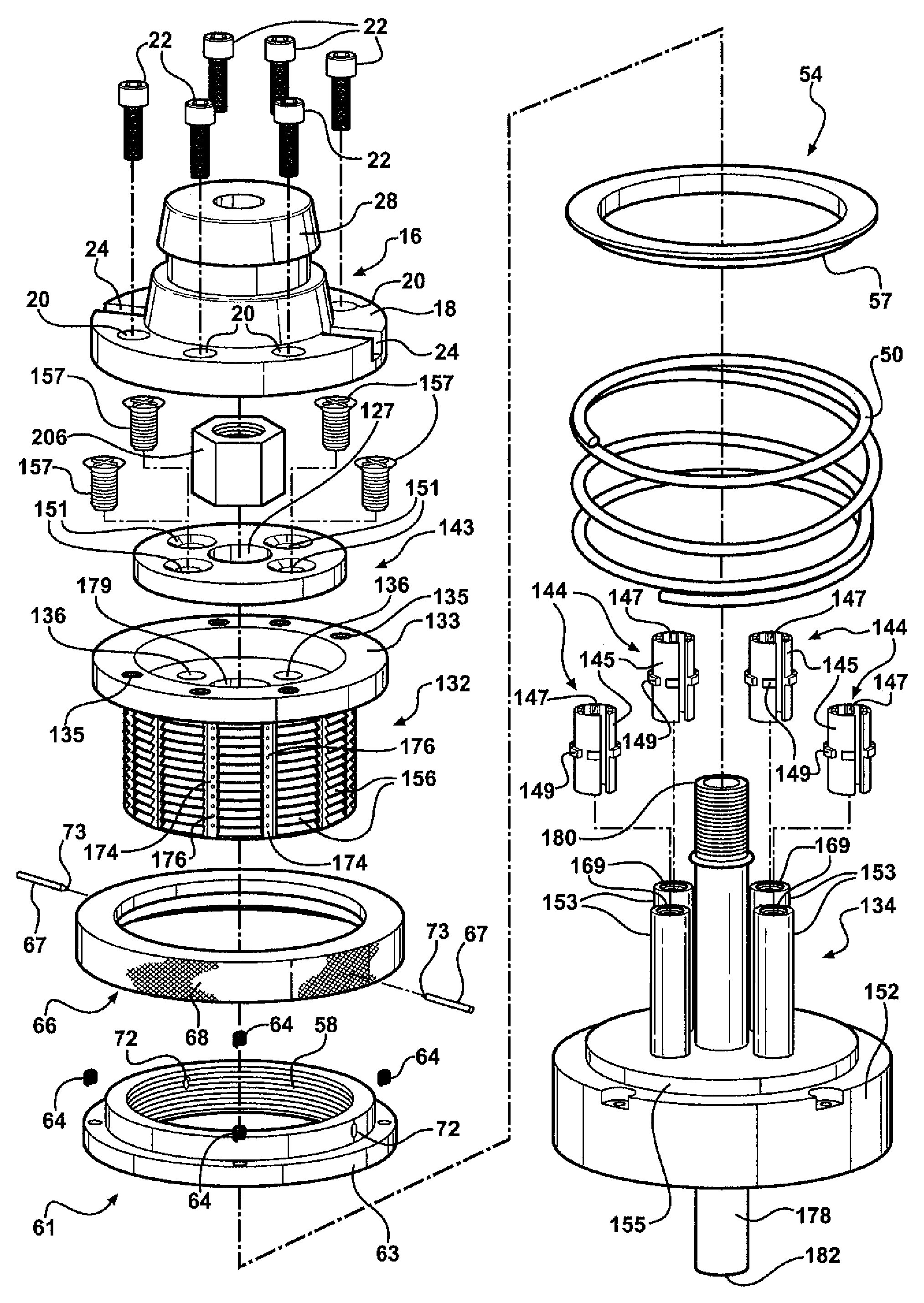
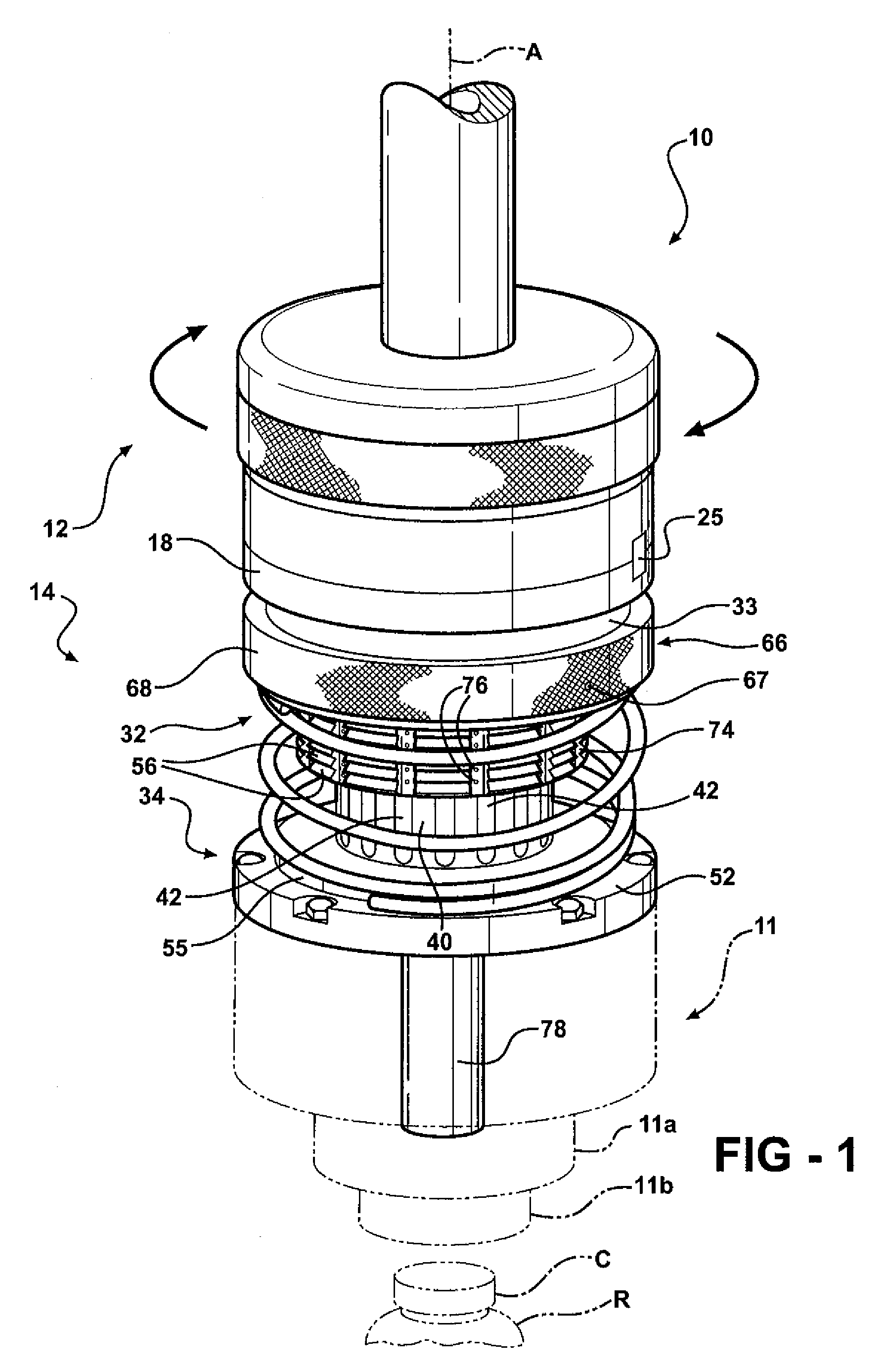
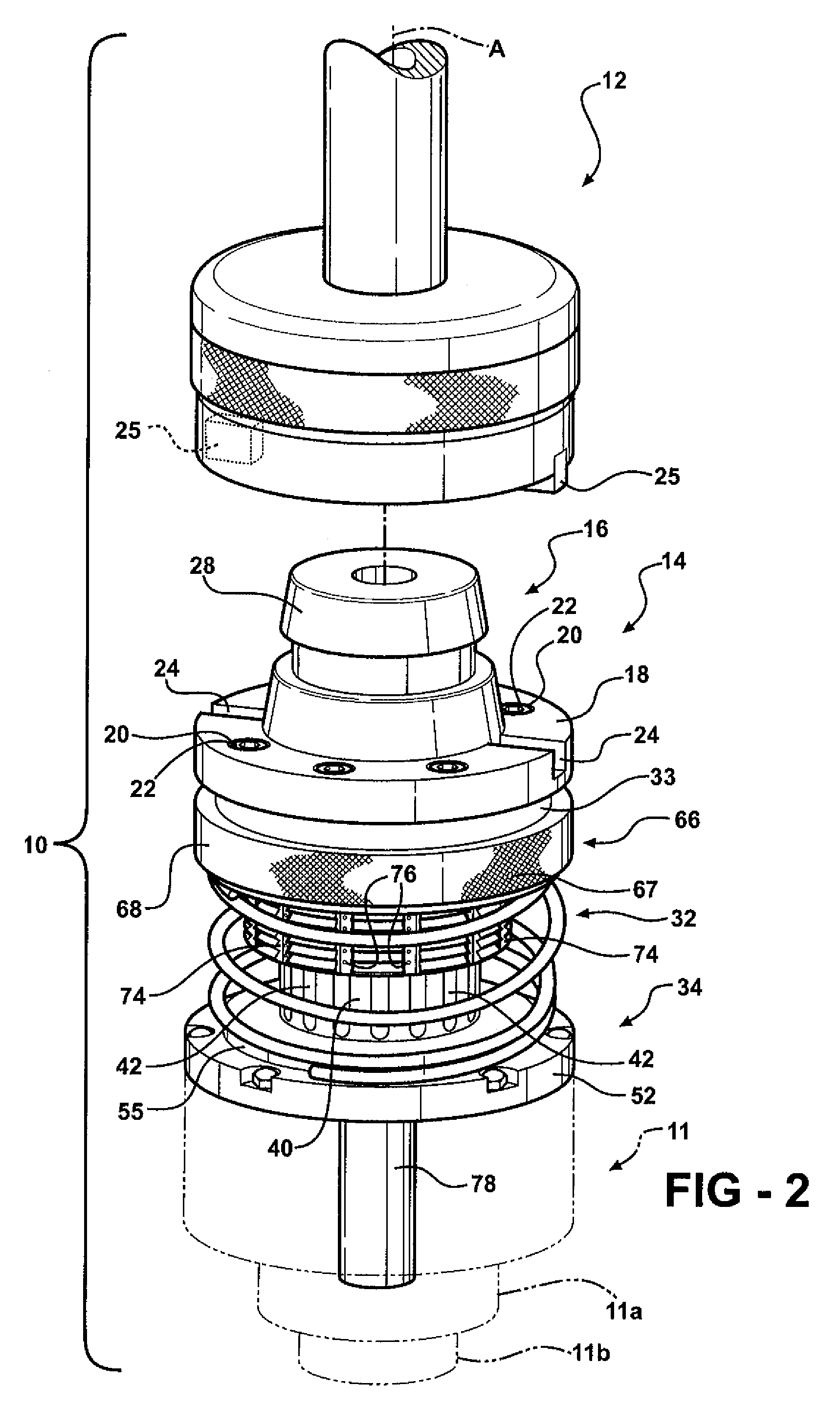
[0019]Referring to the Figures wherein like numerals indicate like or corresponding parts throughout the several views, a capping device is generally shown at 10 in FIGS. 1 and 2. The capping device 10 includes an upper portion 12 and a lower portion 14. As discussed in greater detail below, the upper portion 12 mounts to a capping machine (not shown), which imparts rotation to the capping device 10 about an operational axis A via a drive motor, turret assembly, or other drive source. The lower portion 14 has a capping unit 11 (shown in phantom) mounted at a lower end thereof. The capping unit 11 may comprise a clutch 11a and a cap-engaging portion 11b such as disclosed in U.S. Pat. No. 6,240,678, hereby incorporated by reference. The rotation of the capping device 10 ultimately provides torque to the cap-engaging portion 11b in a conventional manner to thread pre-threaded caps C onto containers R as the containers R and the caps C pass through the capping machine. The capping devic...


PUM


Abstract

A capping device fits caps onto containers by applying an axial force to the caps as they are threaded onto the containers. The capping device utilizes a drive member rotatable about an operational axis for imparting rotation to a capper body slidably coupled to the drive member. A helical spring urges the capper body away from the drive member with a biasing force. A bearing mechanism allows relative free sliding movement of the capper body relative to the drive member. The bearing mechanism includes a plurality of bearing members. In one embodiment, the bearing members are bushings. In another embodiment, the bearing members are ball bearings.

Description

RELATED APPLICATIONS[0001]This application is a continuation-in-part of U.S. patent application Ser. No. 11 / 538,722, filed Oct. 4, 2006, now U.S. Pat. No. 7,331,157, which claims the benefit of U.S. Provisional Patent Application No. 60 / 723,390, filed on Oct 4, 2005, the advantages and disclosure of both applications are hereby incorporated by reference.FIELD OF THE INVENTION[0002]The present invention generally relates to a capping device for fitting pre-threaded caps onto containers, particularly beverage containers. More specifically, the present invention relates to the capping device having a bearing mechanism for allowing relatively free sliding movement between a drive member, which rotates the capping device, and a capper body, which rotates with the drive member and applies the caps onto the containers.BACKGROUND OF THE INVENTION[0003]Capping machines typically utilize multiple capping devices, also known as capping heads or headsets, for fitting pre-threaded caps onto cont...

Claims


Application Information

Patent Timeline
Patent Type & Authority Patents(United States)
IPC IPC(8): B67C3/20
CPCB67B3/2066B67B2201/10
Inventor BROWN, MICHAEL J.
Owner ADCOR INDS
Why Eureka
Try Eureka