Multi-line fluid conduit modules

a fluid conduit and multi-line technology, applied in the direction of transportation and packaging, lighting and heating equipment, heating types, etc., can solve the problems of complex and expensive problems

Inactive Publication Date: 2010-02-16
SIMENSEN THOMAS O +1
View PDF11 Cites 4 Cited by
  • Summary
  • Abstract
  • Description
  • Claims
  • Application Information

AI Technical Summary

Problems solved by technology

Modern hydronic systems, although based on the same concept, incorporate heating, circulation, and control arrangements that would have been unimaginable to the ancients.
Although these arrangements offer some advantages over standard heating and cooling systems, many are complex and expensive.

Method used


Image

  • Multi-line fluid conduit modules
  • Multi-line fluid conduit modules
  • Multi-line fluid conduit modules

Examples


Embodiment Construction

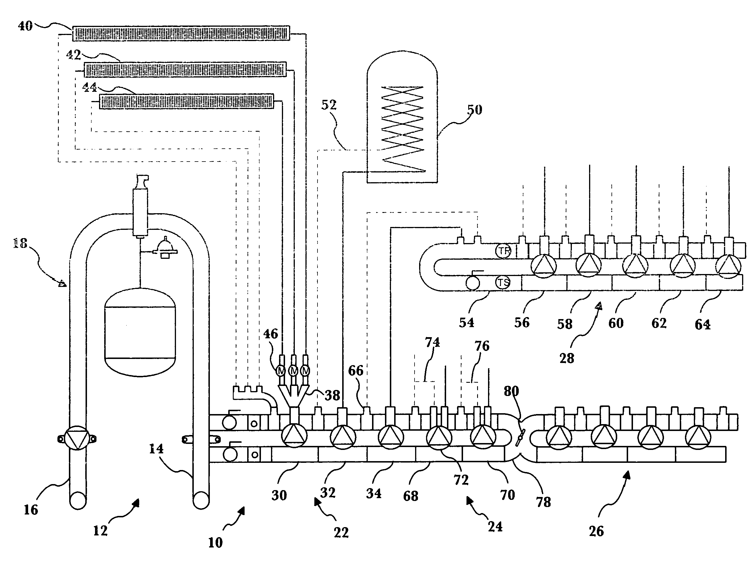
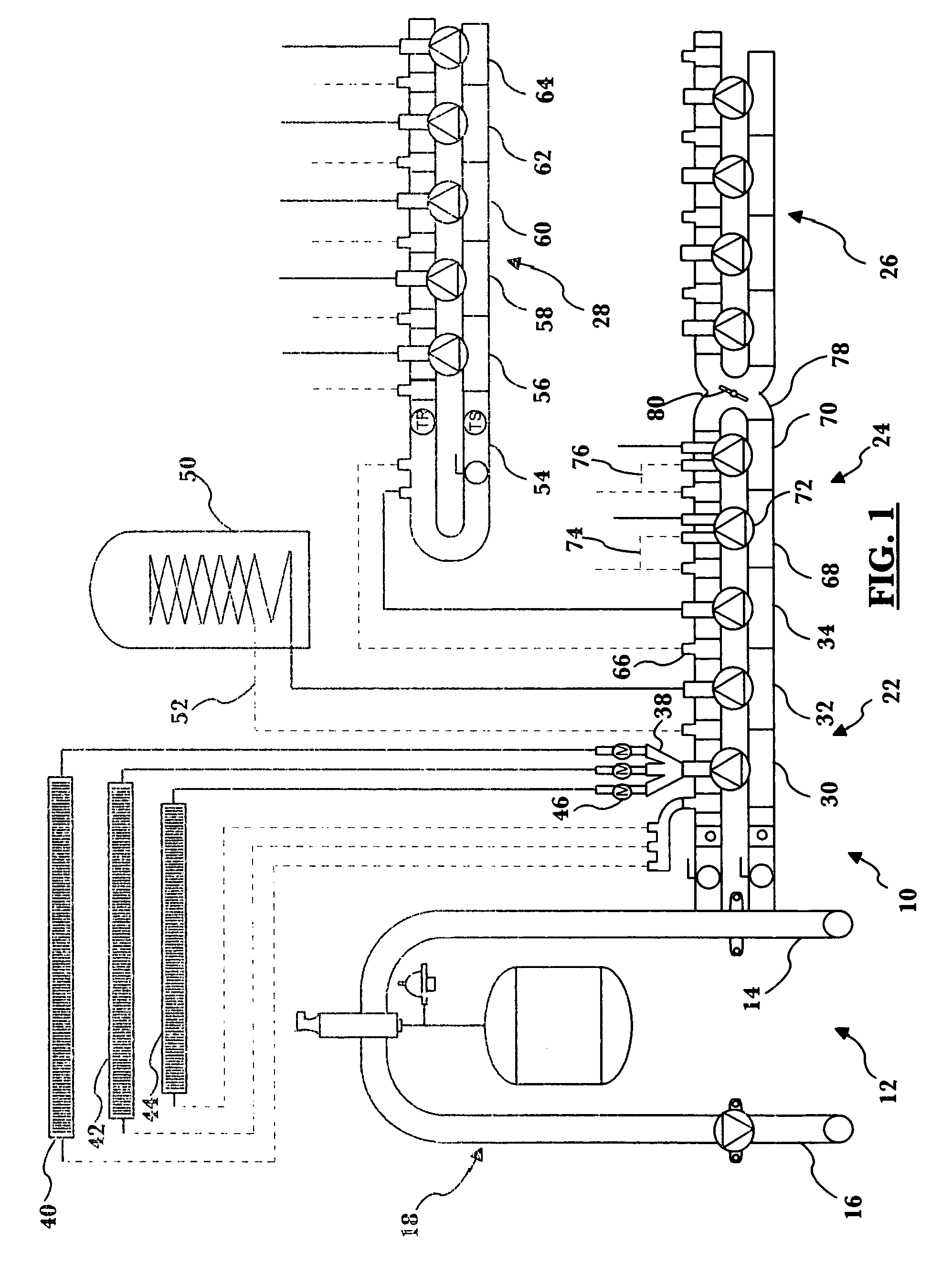
[0016]FIG. 1 illustrates a system 10 incorporating modules embodying the principles of the present invention. The system 10 includes a primary loop module 12 having a boiler supply connection 14, a boiler return connection 16, and an expansion section 18. The primary loop module 12 provides connections from the boiler (not shown) to the heat exchange module groups 22-28, and from the heat exchange module groups 22-28 back to the boiler.

[0017]A first heat exchange module group 22 includes a plurality of high-temperature modules 30, 32, 34. The high-temperature modules typically provide heat exchange medium (such as fluid) at a temperature of around 180 degrees. A baseboard zone module 30 employs a multi-conduit supply manifold 38 to supply heat exchange medium to a plurality of baseboard zones 40, 42, and 44. Each branch of the supply manifold 38 is provided with a motorized valve 46, which can be used to control the flow of heat exchange medium to the respective baseboard zone. Heat...


PUM


Abstract

A modular manifold component for hydronic circulation systems includes a control conduit section adapted and constructed to receive any of a plurality of selectively actuatable fluid control mechanisms. The control conduit section has an inlet and an outlet. A return conduit section is secured to the control conduit section in fluid communication with the inlet of the control conduit section. A supply conduit section is secured to the control conduit section in fluid communication with the inlet of the control conduit section.

Description

FIELD OF THE INVENTION[0001]The invention relates generally to components for systems having fluid conduits. Specifically, the invention relates to modular fluid control components finding particular utility in hydronic heating systems.BACKGROUND OF THE INVENTION[0002]The practice of controlling the temperature of a building by circulating water has been known since the times of the Roman Empire. Archeological reconstruction has revealed that bath houses often used wood-fired boilers to heat water. The hot water was then used not only in the bath itself, but was as well circulated in sub-floor conduits to heat the floor of the bath house.[0003]Modern hydronic systems, although based on the same concept, incorporate heating, circulation, and control arrangements that would have been unimaginable to the ancients. For example, U.S. Pat. No. 5,390,660 to Danielson is directed to a pre-wired and pre-plumbed module for connection to an installed hydronic radiant floor heating system inclu...

Claims


Application Information

Patent Timeline
Patent Type & Authority Patents(United States)
IPC IPC(8): F16K11/10F17D1/00F24D3/10
CPCF17D1/00F24D3/1066Y10T137/5109Y10T137/87885
Inventor SIMENSEN, THOMAS O.SIMENSEN, TORBJORN O.
Owner SIMENSEN THOMAS O
Why Eureka
Try Eureka