Automated spray gun fitted with a spray system mounted on a feed foundation

a spray gun and feed foundation technology, applied in the direction of spray nozzles, gaseous fuel burners, lighting and heating apparatus, etc., can solve the problems of stress very rapidly degrading seals and cutting sheared seals, and achieve the effect of eradicating seal degradation

Active Publication Date: 2010-02-16
CARLISLE FLUID TECH FRANCE SAS
View PDF24 Cites 11 Cited by
  • Summary
  • Abstract
  • Description
  • Claims
  • Application Information

AI Technical Summary

Benefits of technology

[0008]The objective of the present invention is to remedy these drawbacks by creating an improved and quick locking system of a spraygun body onto a foundation to eliminate seal degradation and to preclude any product or pressurized gas leak into the feed conduits.
[0030]Such a tubular socket allows further improving the sealing of the feed conduits of the foundation and of the spraygun body at their junction. Moreover the tubular socket may advantageously act as a positioning means replacing said centering pin because it allows orthogonally engaging, by translation, the spraygun body on the foundation face while affixing, in their plane, the rest face relative to the seating face.

Problems solved by technology

These stresses very rapidly degrade the seals by abrading their surface and the sharp orifice edges entail danger of pinching or cutting the sheared seals.

Method used


Image

  • Automated spray gun fitted with a spray system mounted on a feed foundation
  • Automated spray gun fitted with a spray system mounted on a feed foundation
  • Automated spray gun fitted with a spray system mounted on a feed foundation

Examples


Embodiment Construction

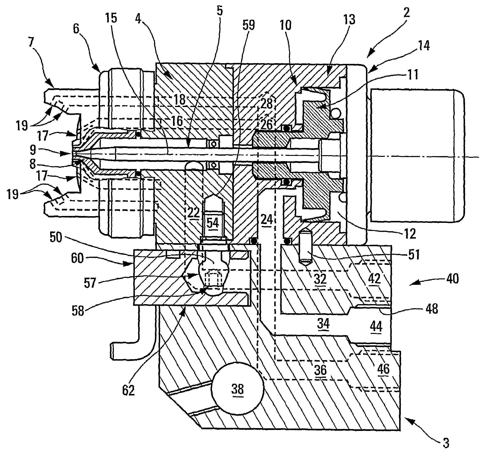
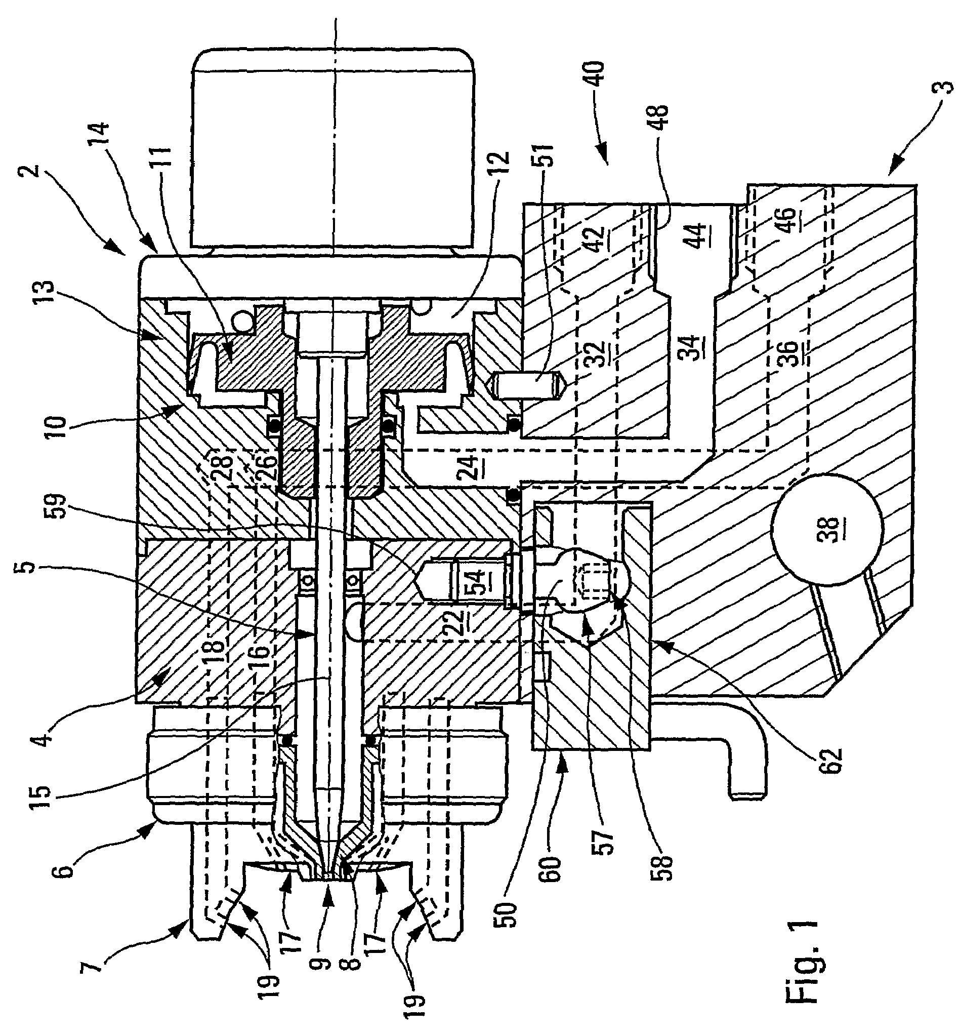
[0038]Generally speaking, the automated spraygun 1 of the invention, which is shown in schematic cross-section in FIG. 1, consists of a spraygun body 2 containing product spray / atomizing means using pressurized gas and assembled onto a foundation 3 connecting feeds of spray product and of pressurized gas (usually compressed air).

[0039]The spraygun body 2 is known and comprises several parts that are assembled in the planes of transverse joints. Be it borne in mind that said body comprises a front part holding a product chamber 5 preceded by a spray head 6 including a gas blowing hood 7 and a nozzle 8 fitted with a spray orifice 9.

[0040]Illustratively the spray head is such as described in the French patent documents FR-A-2,788,231 and FR-A 2,839,663.

[0041]The spraygun body 2 comprises a pneumatic drive compartment 10 having a piston 11 received in a drive compartment chamber 12 in the rear part 13 of the spraygun and sealed by a rear jar 14 fitted with a spray control button. The dr...


PUM


Abstract

An automated spraygun includes a spray / atomization body mounted on a feed foundation. The spraygun includes tensile locking elements between the spray body and the foundation.

Description

RELATED APPLICATIONS[0001]The present application is a National Phase entry of International Application Number PCT / IB2005 / 001921, filed Jul. 6, 2005, which claims priority from, French Application Number 0407749, filed Jul. 12, 2004, the disclosures of which are hereby incorporated by reference herein in their entirety.TECHNICAL FIELD[0002]The present invention relates to an automated spraygun to spray paints, lacquers, enamels or similar products.BACKGROUND OF THE INVENTION[0003]It is known that an automated spraygun comprises a body generally of two or three parts, and a chamber receiving a pressurized product that shall be sprayed and communicating with a spray orifice at the front of the spraygun. This product chamber is crossed by a needle which is fitted at its fore end with a tip able to seal said orifice, said needle being driven by pressurized gas. Moreover the head of the spraygun may be fitted with vents that are situated on each side of the orifice and are fed in parall...

Claims


Application Information

Patent Timeline
Patent Type & Authority Patents(United States)
IPC IPC(8): B05B1/28A01G27/00B05B1/00B05B7/06B05B7/10B05B7/08B05B15/62B05B15/65
CPCB05B7/0815B05B15/065B05B15/061B05B15/62B05B15/65
Inventor VACHER, ERIC
Owner CARLISLE FLUID TECH FRANCE SAS
Why Eureka
Try Eureka