Valve device for fuel tank

Active Publication Date: 2008-03-20
TOYODA GOSEI CO LTD
View PDF31 Cites 10 Cited by
  • Summary
  • Abstract
  • Description
  • Claims
  • Application Information

AI Technical Summary

Benefits of technology

[0016]The invention is accomplished in view of such circumstances. Accordingly, an object of the invention is to reduce the number of components of a valve or a fuel tank to which the valve is mounted, by eliminating the resin seal seat plate, and to assure sealability equal to that in the case of using the rubber seal seat.

Problems solved by technology

The conventional valve device has drawbacks in that the number of components of the valve itself is large, and that the number of steps of a process of assembling the valve device is large.
However, this valve device, which is configured so that both the case and the valve are formed of resins and are of a spherical seal surface structure having the same center of curvature, as described in JP-A-2006-123576, has a problem that even when fuel swelling is small, the position of the seal surface is displaced from a seal contact position at which the valve is sealed, so that the valve is not sealed.

Method used


Image

  • Valve device for fuel tank
  • Valve device for fuel tank
  • Valve device for fuel tank

Examples


example 1

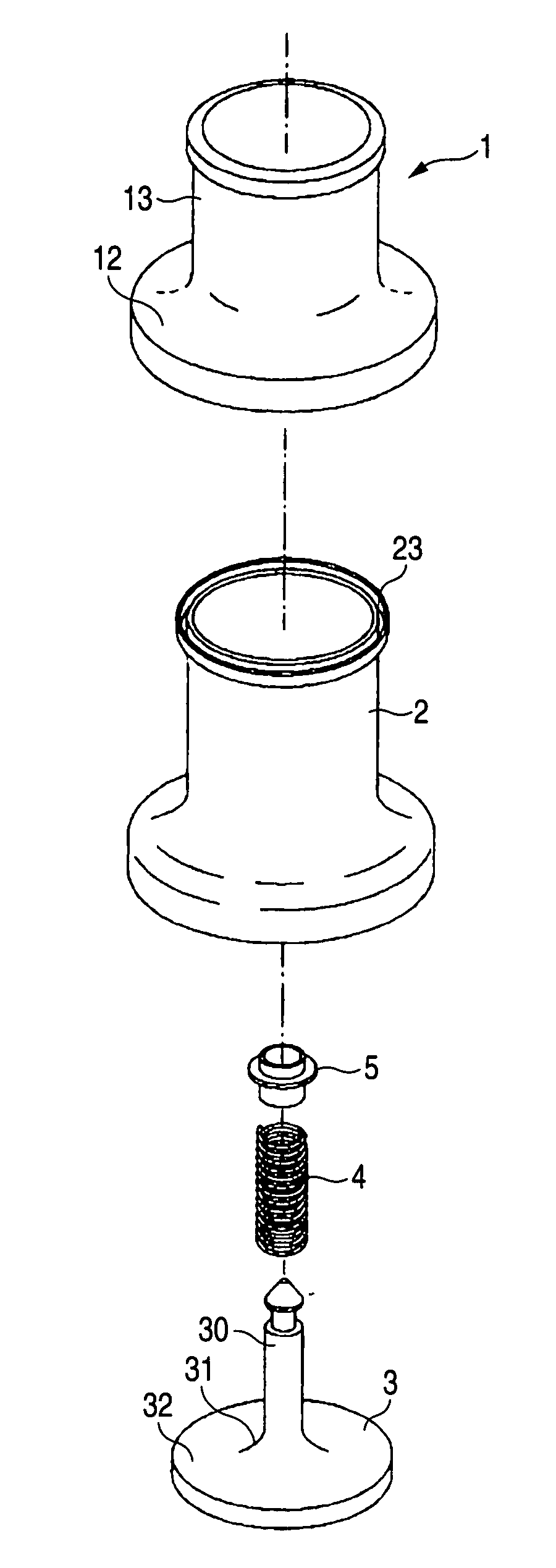
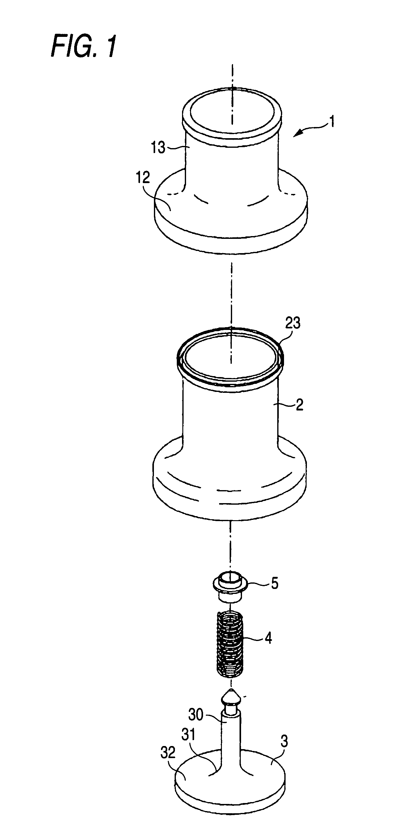
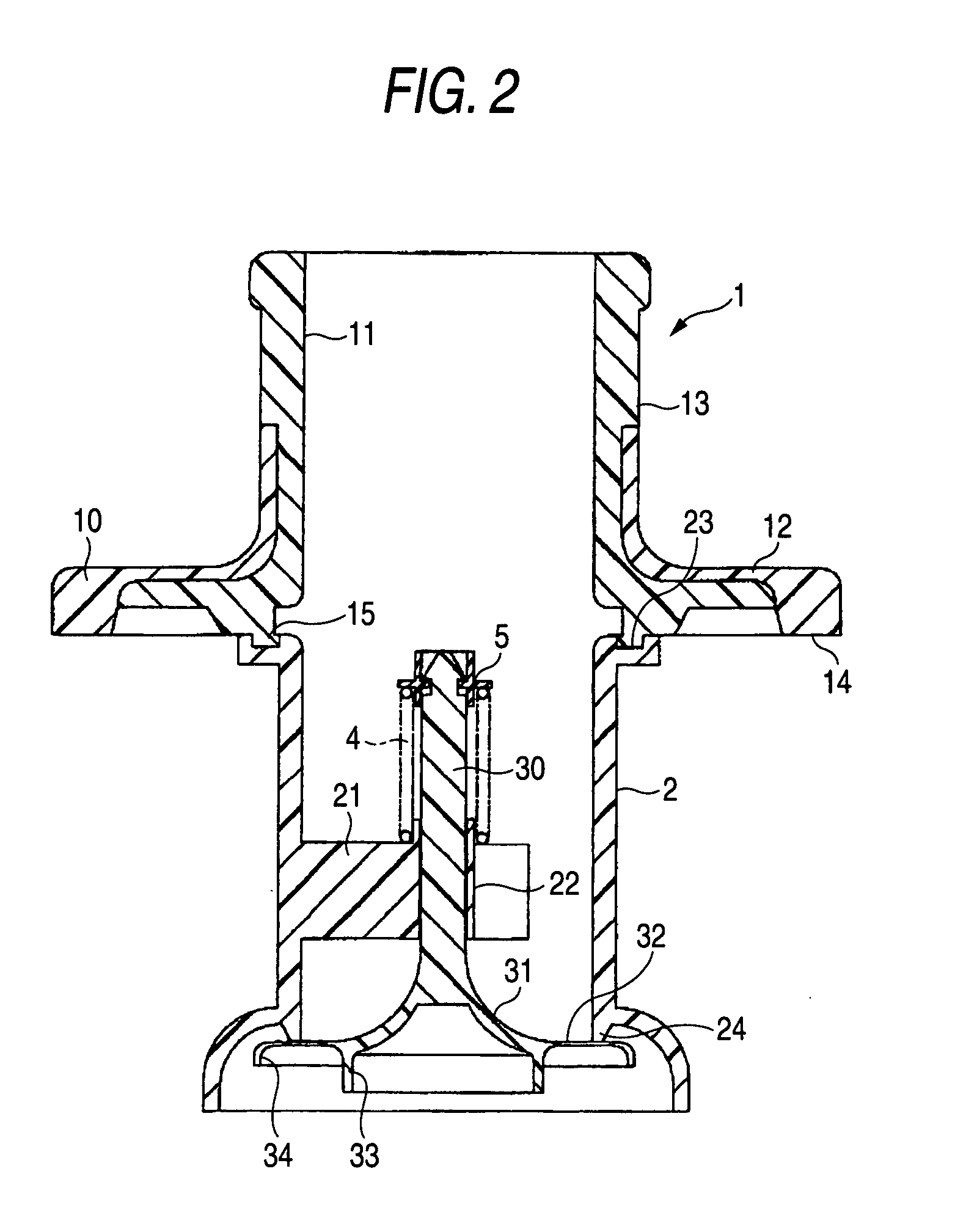
[0048]FIG. 1 shows an exploded perspective view of a valve device according to a first example of the embodiment of the invention. FIG. 2 shows a cross-sectional view of the valve device according to the first example when assembled. This valve device is a backflow prevention valve and includes a cover 1, a case 2, a valve 3, a spring 4, and a cap 5. FIG. 2 illustrates a state in which the valve 3 is depressed against the pushing force of the spring 4.

[0049]The cover 1 has an outer side portion 10 made of maleic acid modified polyethylene, and an inner side portion 11 made of polyamide. The cover 1 is formed by dichromatic molding. Additionally, the cover 1 includes a flange portion 12, and a cylindrical portion 13 protruding from a surface of the flange portion 12. A ring-like first welding portion 14 is formed in a circumferential edge part of the flange portion 12 and is welded to an opening formed in a tank body (not-shown) of a fuel tank. In the examples of the invention, the t...

example 2

[0060]FIG. 6 illustrates a valve device according to the present example of the embodiment. This valve device is similar to the Example 1 except for the shape of a disk portion 32.

[0061]A ring-like groove 35 is formed on a surface of the disk portion 32, which is provided at the side of the shaft portion 30. The depth of the groove 35 is set to be in a range of 0.1 to 0.2 mm. The thickness of the groove 35 is set to be about 0.8 mm. A seal projection 24 is pressure-contacted with the groove 35 to seal the valve.

[0062]According to the valve device of the present example, the seal projection 24 and the groove 35 constitute a labyrinth structure. Consequently, the sealability can be further enhanced.

[0063]Devices, to which the vale device according to the invention is applied, are not limited to the backflow prevention valve. The vale device according to the invention can be utilized for a full tank detection valve, and to flow control valves for breather circuits or for evaporator cir...


PUM


Abstract

A thin disk portion, which extends radially, and a rib provided in an outer circumference part of the disk portion are formed in a valve body. A ring-like seal projection to be pressure-contacted with the disk portion to seal a valve is formed in a case. Because the disk portion is thin, deformation occurs along an end surface of a seal projection when the valve is sealed. Even when the seal projection is deformed due to fuel swelling or the like, sealing is enabled along the entire circumference thereof. High sealability is achieved even when the resin components are pressure-contacted with each other.

Description

BACKGROUND OF THE INVENTION[0001]1. Field of the Invention[0002]The present invention relates to a fuel tank. More specifically, the invention relates to a valve device, such as a backflow prevention valve (or check valve), to be attached to a resin fuel tank.[0003]2. Related Art[0004]Various valve devices, such as a backflow prevention valve, and a valve device for an evaporator circuit, are attached to an automotive fuel tank. In recent years, the resinification of fuel tanks has progressed. Thus, generally, these valve devices are joined to the resin fuel tank by welding.[0005]To prevent fuel contained in a fuel tank from backflowing into a fuel feed pipe, a backflow prevention valve is interposed between the fuel tank and the fuel feed pipe. As illustrated in, for example, FIGS. 7 and 8, the backflow prevention valve consists of a cover 100, a case 200, a valve 300, and a spring 400.[0006]The cover 100 has an outer side portion 101 made of maleic acid modified polyethylene, and ...

Claims


Application Information

Patent Timeline
IPC IPC(8): F16K1/32B65D88/00B65D90/02
CPCF16K15/063Y10T137/86372
Inventor KOBAYASHI, YOSHITAKAKANEKO, KENICHIRO
Owner TOYODA GOSEI CO LTD
Why Eureka
Try Eureka