Substrate carrier

Active Publication Date: 2005-05-26
ENTEGRIS INC
View PDF20 Cites 5 Cited by
  • Summary
  • Abstract
  • Description
  • Claims
  • Application Information

AI Technical Summary

Benefits of technology

[0012] Unlike prior art containers which utilize a robotic-flange attachment at the top wall of the container, interfaces with a robotic end-effector for lifting the container during transport or transfer, a feature and advantage of the instant invention is the robotic flange, although located on top of the container and forming an interface via which the robotic end-effector lifts the wafer container, in a preferred embodiment the flange is not rigidly attached to the top wall of the container. Instead, the robotic-flange is a component of a lift-saddle. The lift-saddle is comprised of a pair of straps, each strap is fixedly attached to a lateral side of the robotic flange and drapes along a lateral wall of the container. Each strap has a plurality of strap engagement members configured to engage with corresponding support brackets on the lateral side walls of the container shell whereby the load on the robotic-flange is transferred, via the straps, to the lateral side walls of the container. This arrangement prevents the load induced distortion of the top shell wall and eliminates the consequent FOUP / FOSB seal burping.

Problems solved by technology

Many of these operations require a clean room environment devoid of airborne particulates and other contaminants which would seriously compromise the quality of the end product.
Because electrostatic discharges can damage or ruin semiconductor wafers, static electricity is a continuing concern in the handling and processing of such wafers.
Furthermore, the use at any location in the pod of metallic fasteners or other metal parts are highly undesirable in semiconductor wafer carriers or containers.
Metallic parts generate highly damaging particulates when rubbed or scraped.
Assembly of a module with fasteners causes such rubbing and scraping.
However, due to inconsistencies in molding plastic parts, assembly of such plastic parts lead to inconsistencies, such as open cracks between parts and the stacking of the tolerances of each individual part leading to undesirable variations in critical dimensions.
In either case, lifting the container using the handle induces stresses in the top wall of the enclosure.
Depending on this stress profile, the resulting strains could cause a deformation mode of the top wall which distorts the dimensions of the opening on the front side of the module where it engages with the front door leading to the burping of the FOUP / FOSB seal and a breach of the sealed enclosure.

Method used


Image

  • Substrate carrier
  • Substrate carrier
  • Substrate carrier

Examples


Embodiment Construction

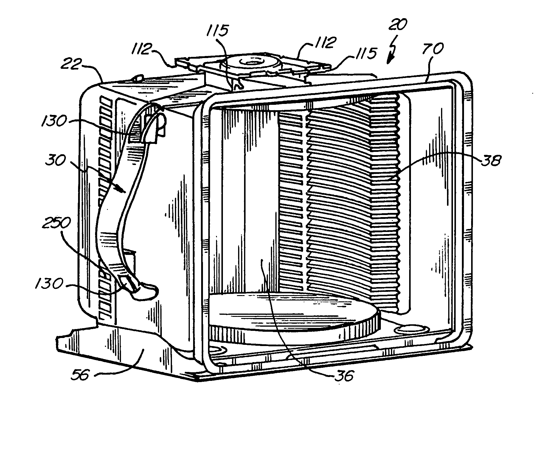
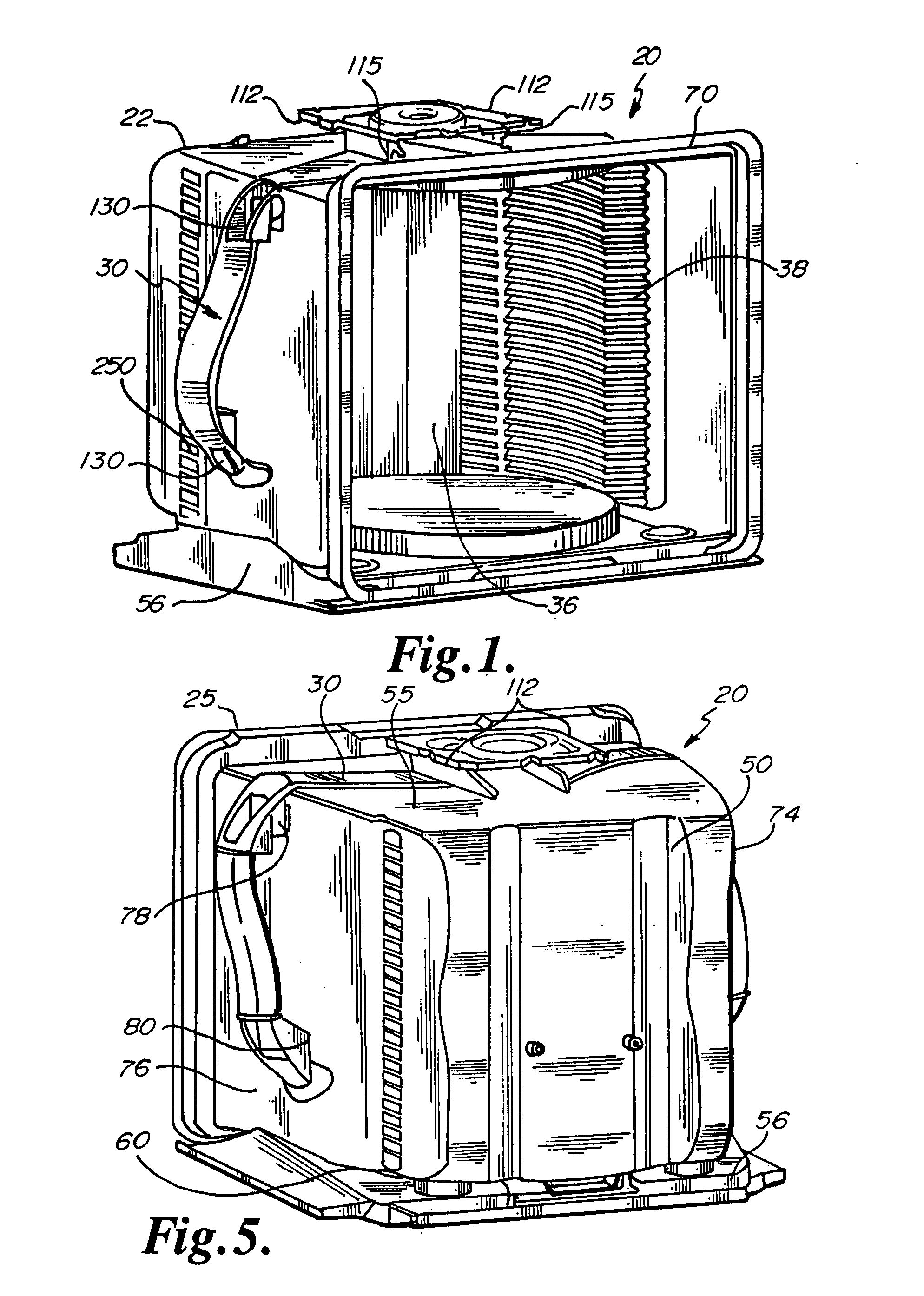
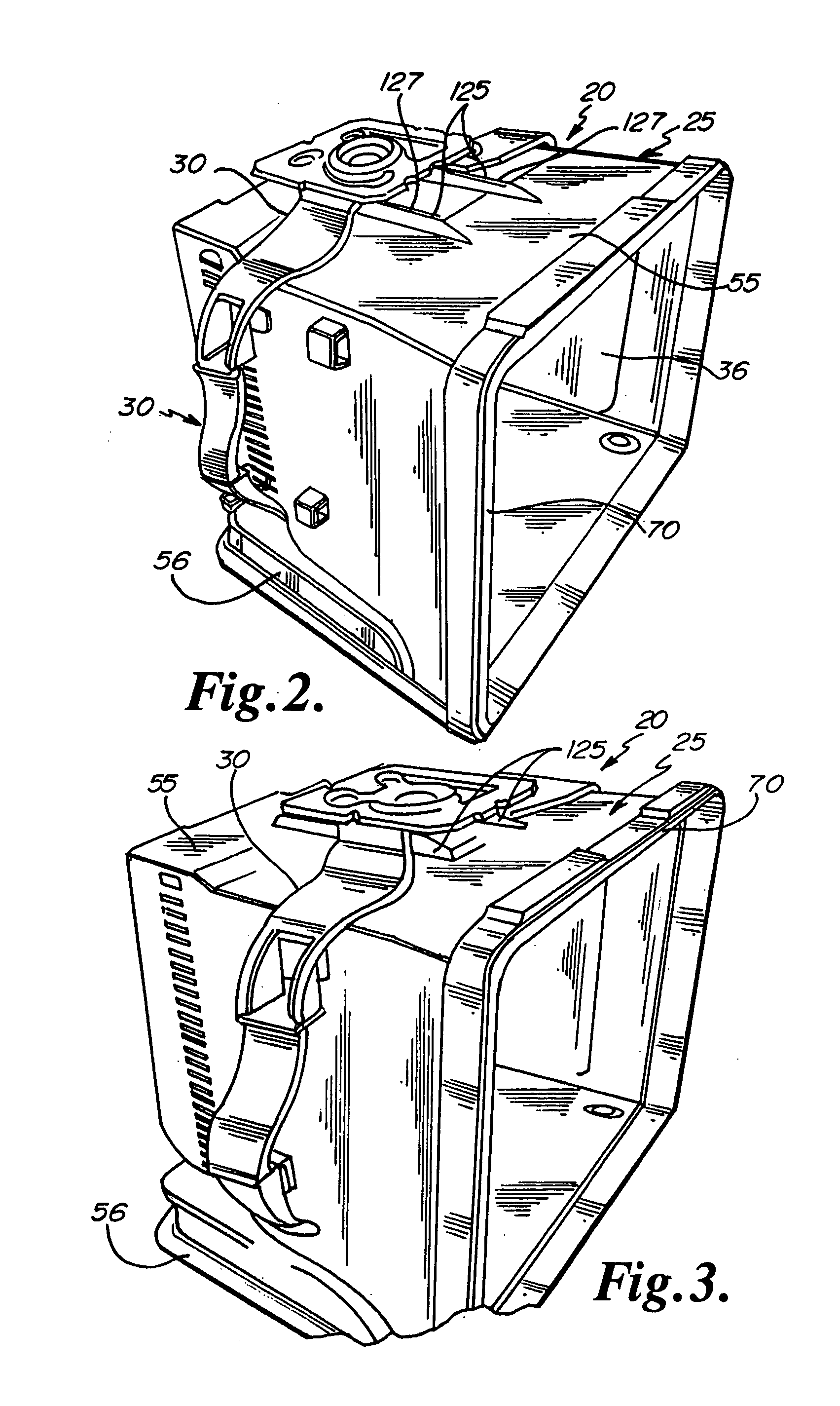
[0022] Referring to FIGS. 1, 2, 3, 4 and 5 a container module for wafers generally designated with the numeral 20 is principally comprised of a container portion 25 and a lift-saddle 30.

[0023] The container portion 25 is comprised principally of a shell 50 which has a top wall 55, a bottom wall 60, an open front side 70, a left side wall 74, and a right side wall 76 both with lift-saddle receiving portions configured as “U” shaped loops 78 and 80 extending outwardly from each side wall. The sidewalls are continuous and solid. FIGS. 1 and 2 show the open interior 36 of the container with a plurality of wafer retainers 38 axially arranged in said open interior. The wafer retainers are formed of flexible teeth 44 which are of resilient molded plastic. FIG. 2 also depicts a conductive plate 56 on which the container 25 is supported. In a preferred embodiment, the conductive plate 56 is electrically grounded and is designed with three interface structures that comprise a kinematic coupl...


PUM


Abstract

A carrier for transporting silicon semiconductor wafers during semiconductor wafer processing operations including an enclosure, a door and a flange structured to interface with a machine so that the carrier can be lifted by the machine. A lift saddle connects the flange to the container so that the load on the flange is transferred to a part of the enclosure other than the top of the enclosure to prevent distortion of the enclosure to maintaining seal integrity between the enclosure and the door.

Description

[0001] This application claims the benefit of U.S. Provisional Application Ser. No. 60 / 514,040 filed Oct. 24, 2003, the same being incorporated herein by reference.FIELD OF THE INVENTION [0002] This invention relates to semiconductor wafer processing equipment, and more particularly to silicon wafer carriers used to protectively house a plurality of semiconductor wafers for automated handling during semiconductor wafer processing operations. BACKGROUND OF THE INVENTION [0003] The manufacture of an integrated circuit involves a plurality of operations on wafers of semiconductor substrates. Some of the operations may include processing steps such as photolithography, etching, exposure, as well as inspection and testing of the wafer as it is being formed into the desired end product. Some of these operations involve automated material handling and processing using robotic end-effectors. Many of these operations require a clean room environment devoid of airborne particulates and other ...

Claims


Application Information

Patent Timeline
IPC IPC(8): B65D85/00H01L
CPCH01L21/67379H01L21/67383Y10S206/832Y10T16/4707Y10T16/469H01L21/68
Inventor BURNS, JOHNFULLER, MATTHEW A.KING, JEFFERY J.FORBES, MARTIN L.SMITH, MARK V.ZABKA, MICHAEL
Owner ENTEGRIS INC
Why Eureka
Try Eureka