
Device for vehicle seat

a vehicle seat and seat back technology, applied in the direction of chairs, movable seats, transportation and packaging, etc., can solve the problems of user discomfort, impossibility, and inability to achieve expected comfort in some cases, and achieve the effect of improving safety and confirming the safety behind the seat back

Active Publication Date: 2010-02-16
MAZDA MOTOR CORP
View PDF39 Cites 20 Cited by
  • Summary
  • Abstract
  • Description
  • Claims
  • Application Information

AI Technical Summary

Benefits of technology

The present invention relates to a device for a vehicle seat that allows for safe and easy manipulation of the seat back. The device includes an electric motor for raising the seat back and a combination of a momentary manipulation switch and a mechanism for stopping the seat back from rising too high. The device also includes a compulsory cutting mechanism that prevents the seat back from being raised too high. The invention aims to provide a device that allows for a seat back to be raised while still maintaining safety and comfort for the user.

Problems solved by technology

Accordingly, even if the user determines the raised angle of the seat back at a degree that the user thinks it comfortable and stops the electric motor to set the seat back at the determined angle, expected comfortableness would not be obtained in some cases.
For example, the seat back is raised excessively to cause the user to feel uncomfortable or is reclined so backward to cause the user to feel uncomfortable and to narrow the luggage space behind the seat back.
Even in such a case, however, the user may release his / her hand too early or too late, which invites impossibility to stop the seat back at the desired raised position without failure.
In this case, however, large force is applied to the seat back, the stopper, and the like until the electric motor is stopped from the time when the seat back abuts on the stopper, and therefore, the device for the seat vehicle is liable to be broken.
This reinforcement, however, involves an increase in weight of the vehicle.
Further, it takes considerable time from the time when the activation switch is turned on to the time when the electric motor is activated, the seat back is folded forward, and then, the electric motor is stopped.
Therefore, quick forwardly folding of the seat back cannot be attained.
Further, employment of the electric motor for forwardly folding the seat back increases power consumption in the automobile.
However, the electric motor for raising the seat back restrains forwardly folding of the seat back because the electric motor engages with the seat back or the vehicle (or the seat cushion) through transmitting means, such as a gear.
In this case, not only restraint of the electric motor but also the friction resistance applied cause difficulty in setting the seat back to the predetermined forwardly folded state only by the biasing means, such as a spring or the like.

Method used


Image

  • Device for vehicle seat
  • Device for vehicle seat
  • Device for vehicle seat

Examples


Embodiment Construction

[0106]An embodiment of the present invention will be described below with reference to the accompanying drawings.

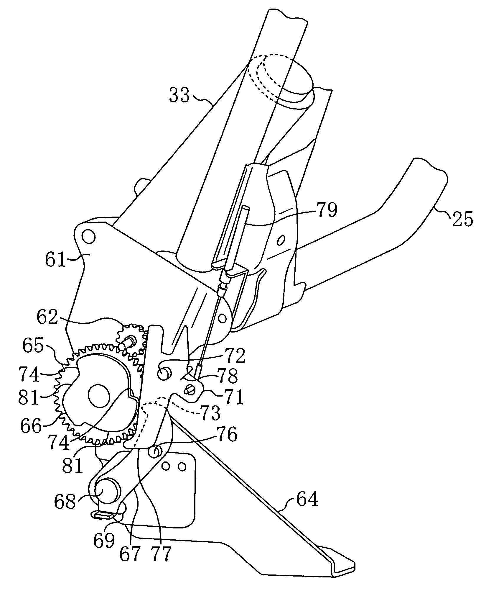
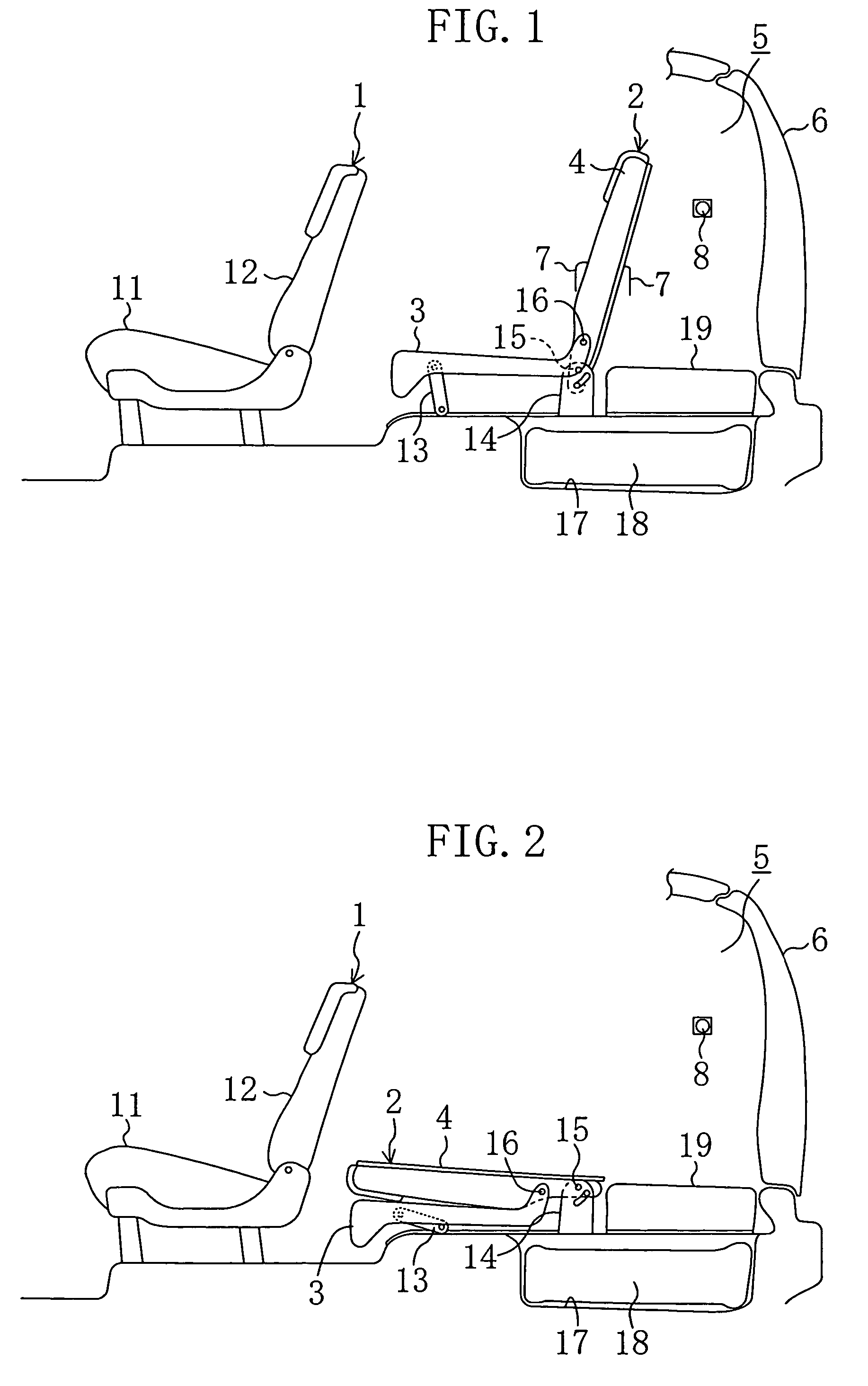
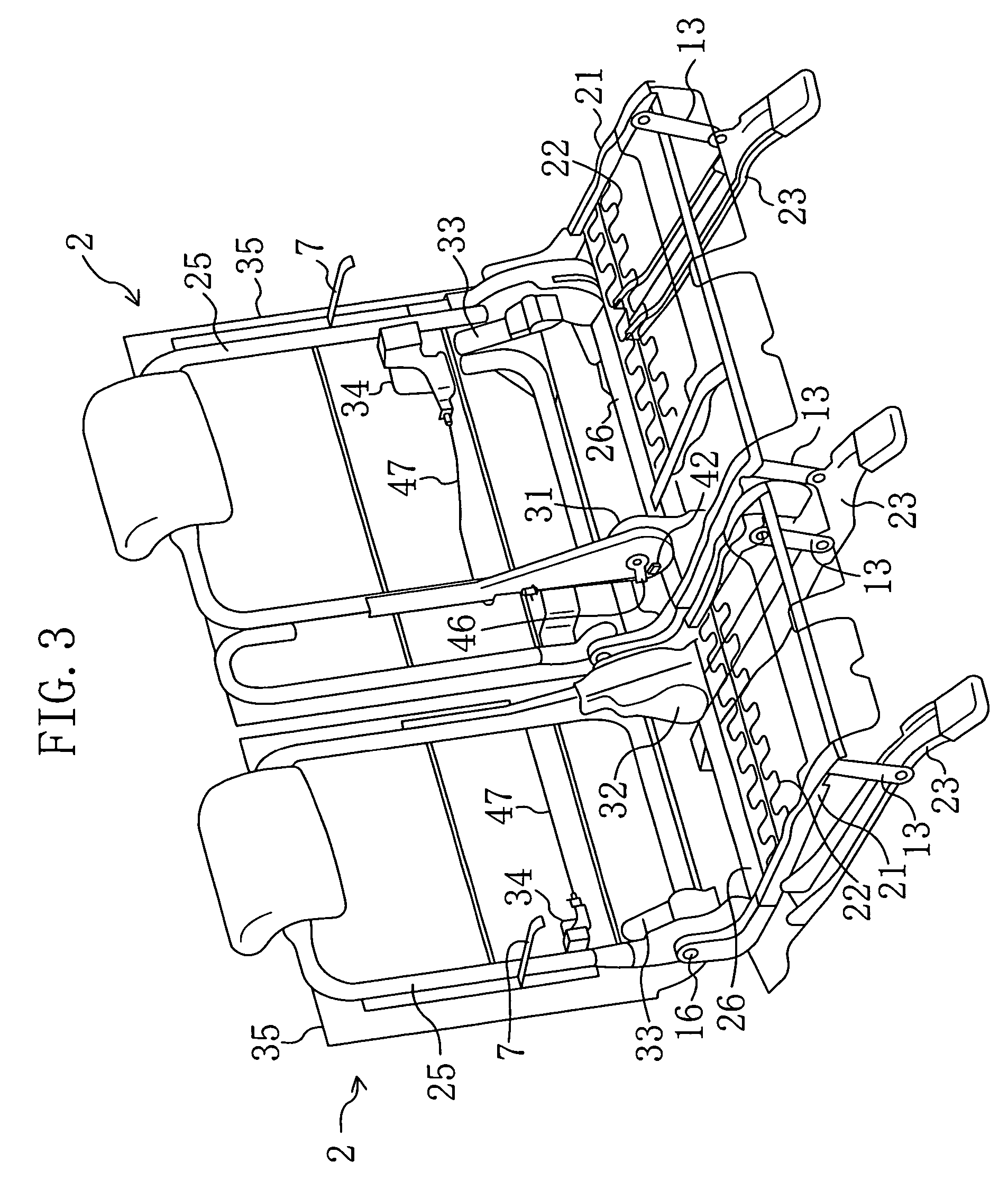
[0107]FIG. 1 shows a rear part of a vehicle (an automobile) including three rows of seats arranged in back and forth directions. In detail, FIG. 1 shows an intermediate seat 1 and a back seat 2, and a front seat including a driver's seat is not shown. In the state where a seat back 4 of the back seat 2 is raised, a luggage compartment 5 is formed behind the seat back 4. In other words, the raised seat back 4 partitions the vehicle cabin into a passenger compartment in the front part and the luggage compartment 5 in the rear part. A baggage can be loaded or unloaded from the back of the vehicle after a back door 6 at the back of the vehicle is opened. Further, a side door is provided on each side (outer side in a car width direction) of the intermediate seat 1, and a passenger can open the side door and get on or off the vehicle to sit on the intermediate seat 1 or the bac...


PUM


Abstract

When a seat back in a forwardly folded state is raised to a predetermined raised state by activating an electric motor by turning on a switch, the electric motor is immediately stopped even if the switch is still turned on, and the seat back is retained in the raised state. There are provided a locking member which operates to retain the seat back in the raised state when the seat back is in the predetermined raised state and a lever which turns in association with the operation of the locking member. The lever turns on another switch to open a drive circuit for the electric motor.

Description

CROSS REFERENCE TO RELATED APPLICATIONS[0001]This Non-provisional application claims priority under 35 U.S.C. § 119(a) on Patent Application Nos. 2005-272577, 2005-272581, and 2005-272588, each filed in Japan on Sep. 20, 2005, the entire contents of which are hereby incorporated by reference.BACKGROUND OF THE INVENTION[0002]1. Field of the Invention[0003]The present invention relates to a device for a vehicle sheet.[0004]2. Background Art[0005]In a cabin structure of a vehicle, such as an automobile or the like, it is generally known as disclosed in Japanese Patent Application Laid Open Publication No. 2001-239870A to divide the cabin into a passenger compartment and a luggage compartment at the back of the cabin by a sheet back of the rearmost seat of a plurality of seats arranged back and forth and to fold the seat back forward so as to be laid over a seat cushion for using the upwardly facing back of the seat back as a luggage table, namely, so as to expand the luggage space towa...

Claims


Application Information

Patent Timeline
Patent Type & Authority Patents(United States)
IPC IPC(8): A47C4/12
CPCB60N2/0232B60N2/20B60N2/236B60N2/3065B60N2/3013B60N2/02246
Inventor NAKAYA, KOUICHIMURAMATSU, KENJI
Owner MAZDA MOTOR CORP
Learn More