Centipede actuator motion stage

a technology of actuators and motion stages, applied in the field of micro electro mechanical actuators, can solve the problems of complicated assembly and a lot of components, and achieve the effect of limiting motion and preventing contamination of actuators

Active Publication Date: 2010-02-16
DIGITALPTICS MEMS
View PDF8 Cites 20 Cited by
  • Summary
  • Abstract
  • Description
  • Claims
  • Application Information

AI Technical Summary

Benefits of technology

[0009]In one embodiment, the stage contains all required elements needed to provide repeatable actuated motion of the mount. This includes springs or flexures to provide a repeatable restoring force, guiding to

Problems solved by technology

These systems have a lot of components and r

Method used


Image

  • Centipede actuator motion stage
  • Centipede actuator motion stage
  • Centipede actuator motion stage

Examples


Embodiment Construction

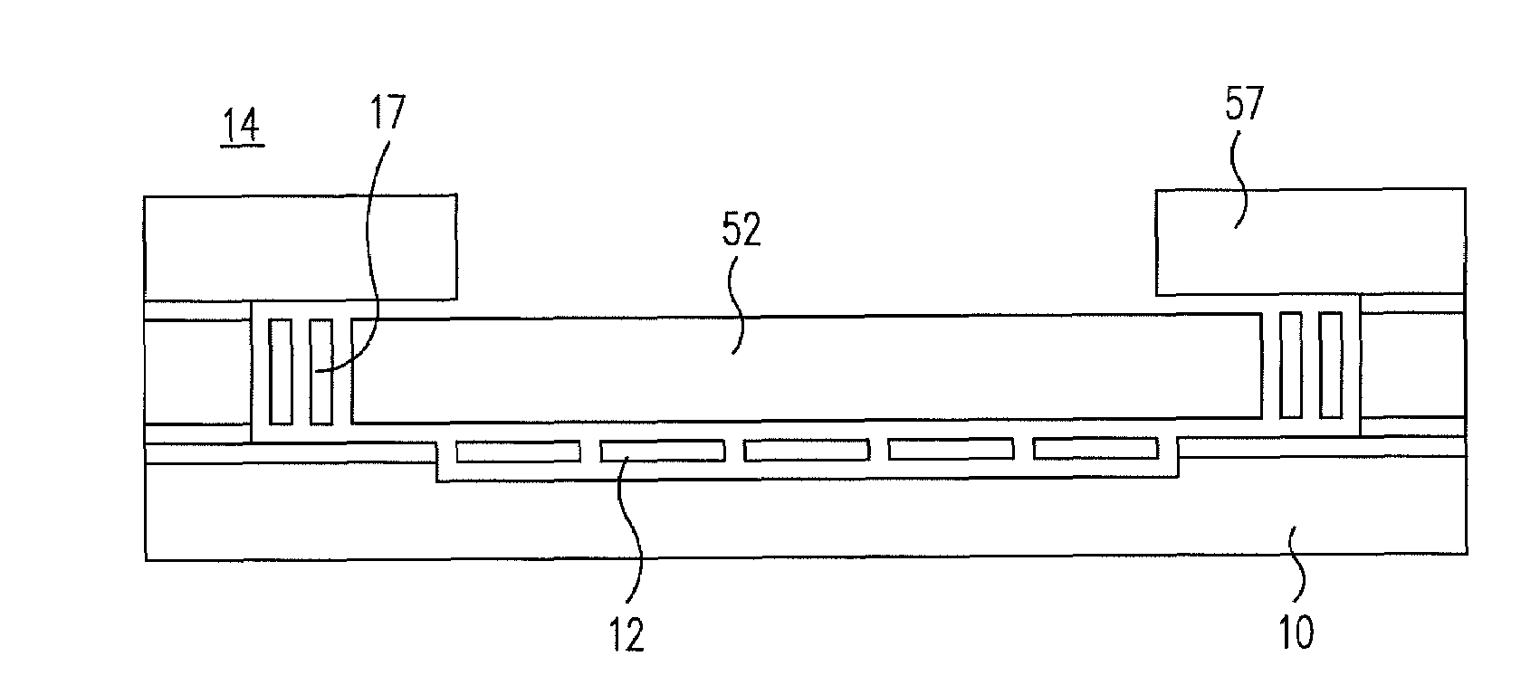
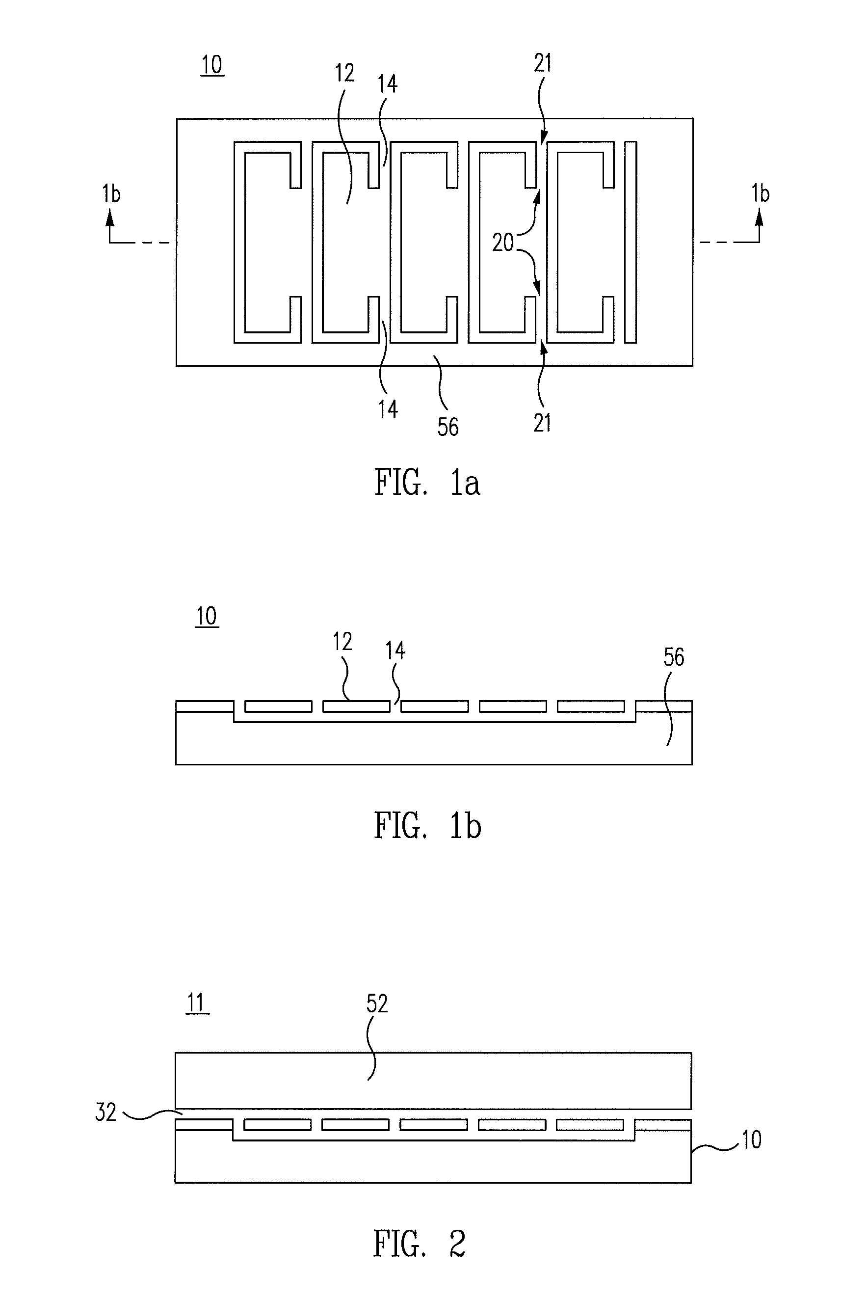
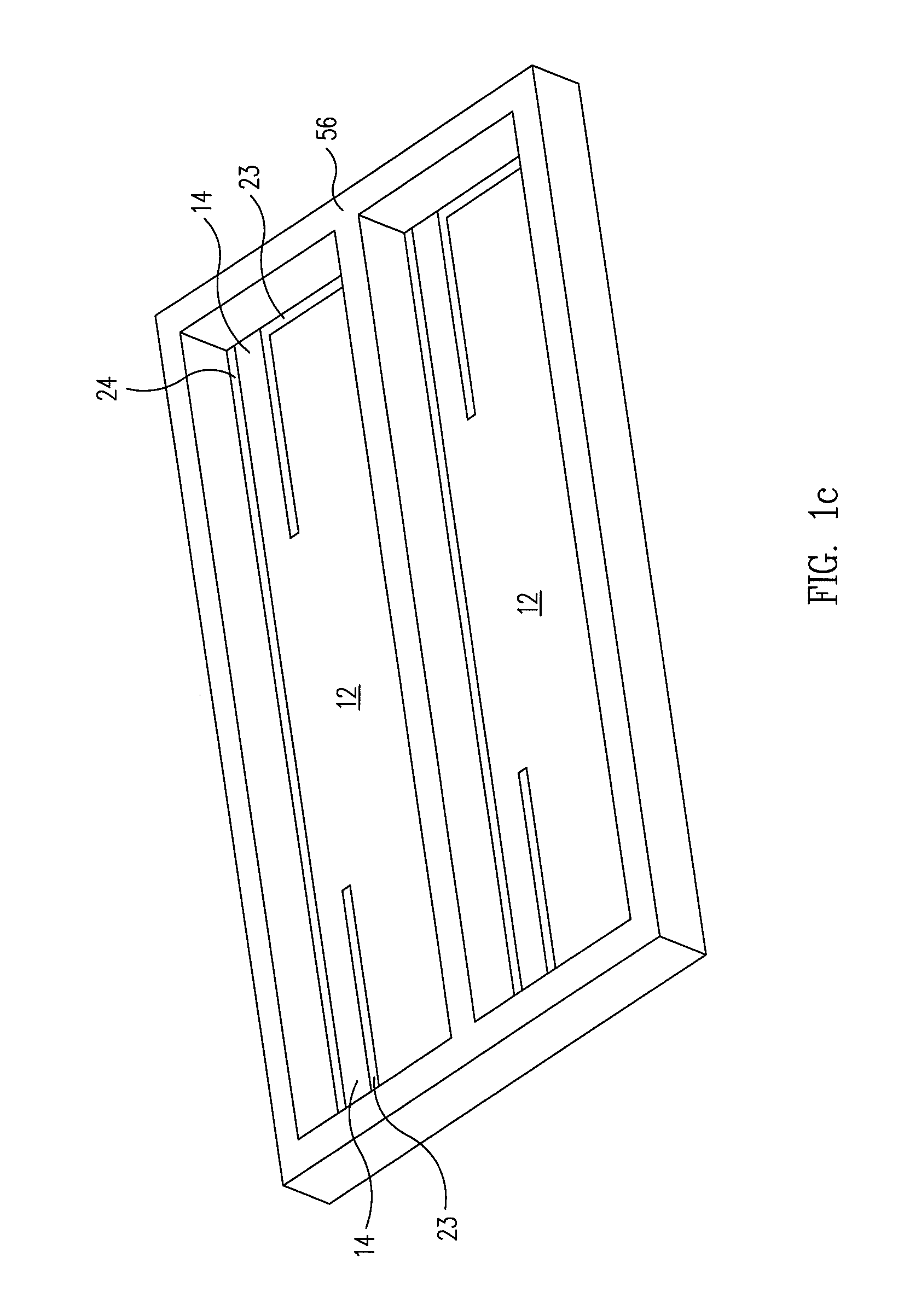
[0030]FIG. 1a shows a top view of a base plate 10 according to one embodiment of the present invention. The base plate 10 is composed of a substrate 56 and an array of movable elements or flaps 12. Five flaps 12 are shown, although more or less flaps may be suitable for different applications. Each flap 12 is supported to the substrate through two flexures 14 (see also FIG. 1c). The flexures 14 are designed in such a way as to be very soft in rotation about the axis of the flexure and motion in a direction perpendicular to the plane of the substrate 56. All other degrees of freedom are relatively stiff. This can be achieved, for example, by a flexure 14 that is about 1 micron to 5 microns thick in the direction orthogonal to the plane of the substrate 56. Each flexure 14 may be 5 microns to 10 microns wide and 20 microns to 200 microns long. The length of the flexure is measured from the end 20 of the etched portion to the side 21 of the etched portion (see FIGS. 1a and 1c). Clearly...


PUM


Abstract

A micro electromechanical actuator has movable flaps formed on a base plate. The flaps are detached from the base plate on the ends and along one side, with the opposite side being partially attached to the base plate by flexures. The flaps can be moved upward, rotating or twisting along the axis of the flexure so that a one side contacts a movable element first, followed by the opposite side. As a result, the movable element is moved laterally with respect to the flaps. Movement of the flaps can be by application of a voltage to the flaps, followed by removal of the voltage to return the flaps to their original position. The cycle can continue to move the movable element the desired amount.

Description

RELATED APPLICATIONS[0001]The present application claims priority to provisional application Ser. No. 60 / 546,100, filed Feb. 18, 2004, entitled “Centipede Actuator Motion Stage”.BACKGROUND OF THE INVENTION[0002]1. Field of the Invention[0003]The present invention relates to actuators, and in particular micro electro mechanical (MEM) actuators.[0004]2. Related Art[0005]There is a recent surge of interest in camera systems for cell phone and other portable devices. This market has pushed the limits of standard optical systems in providing high quality zoom lens systems in a small package and at low cost. Current state-of-the art zoom lens systems use plastic and other low cost components to assemble moving lens assemblies. The motion of these lenses is typically driven using small electric motors. These systems have a lot of components and require complicated assembly to put together.[0006]There is a need for an integrated actuated stage, where the actuator, the springs, and the guide...

Claims


Application Information

Patent Timeline
IPC IPC(8): H02N1/00
CPCH02N1/006
Inventor GUTIERREZ, ROMAN C.
Owner DIGITALPTICS MEMS
Why Eureka
Try Eureka