Magnetic resonance imaging apparatus and analysis method for fat suppression effect in magnetic resonance imaging apparatus

a magnetic resonance imaging and imaging apparatus technology, applied in the direction of diagnostic recording/measuring, using reradiation, instruments, etc., can solve imaging cannot sufficiently eliminate the spatial inhomogeneity of a fat suppression effect in some cases, and the inability to correct the spatial inhomogeneity of the fat suppression effect caused by the spatial inhomogeneity of a radio-frequency magnetic field, etc., to achieve the effect o

Inactive Publication Date: 2010-02-16
TOSHIBA MEDICAL SYST CORP
View PDF15 Cites 8 Cited by
  • Summary
  • Abstract
  • Description
  • Claims
  • Application Information

AI Technical Summary

Problems solved by technology

In any of these fat suppression methods, spatial inhomogeneity of a fat suppression effect occurs.
Therefore, a correction current set based on a spatial distribution of a magnetic field measured before imaging cannot sufficiently eliminate spatial inhomogeneity of a fat suppression effect in some cases.
Furthermore, since spatial inhomogeneity of the fat suppression effect based on a static magnetic field distribution is corrected, spatial inhomogeneity of the fat suppression effected caused due to spatial inhomogeneity of a radio-frequency magnetic field cannot be corrected.
That is, the conventional technology cannot prevent spatial inhomogeneity of the fat suppression effect involved by spatial inhomogeneity of a radio-frequency magnetic field or a eddy magnetic field from affecting an image.
Meanwhile, spatial inhomogeneity of a radio-frequency magnetic field or a eddy magnetic field varies depending on each apparatus due to, e.g., malfunction of the apparatus, a manufacturing error of a gradient magnetic field coil or an RF coil, or good or poor results of apparatus adjustment in an installing operation or a maintenance operation.
Therefore, when spatial inhomogeneity of the fat suppression effect prominently appears in an image taken by a given apparatus, great labor is required to confirm whether a phenomenon can be improved while sequentially taking countermeasures from which effects are likely to be expected (adjustment or component replacement) in regard to each of the above-explained factors.

Method used


Image

  • Magnetic resonance imaging apparatus and analysis method for fat suppression effect in magnetic resonance imaging apparatus
  • Magnetic resonance imaging apparatus and analysis method for fat suppression effect in magnetic resonance imaging apparatus
  • Magnetic resonance imaging apparatus and analysis method for fat suppression effect in magnetic resonance imaging apparatus

Examples


Embodiment Construction

[0031]An embodiment according to the present invention will now be explained hereinafter with reference to the accompanying drawings.

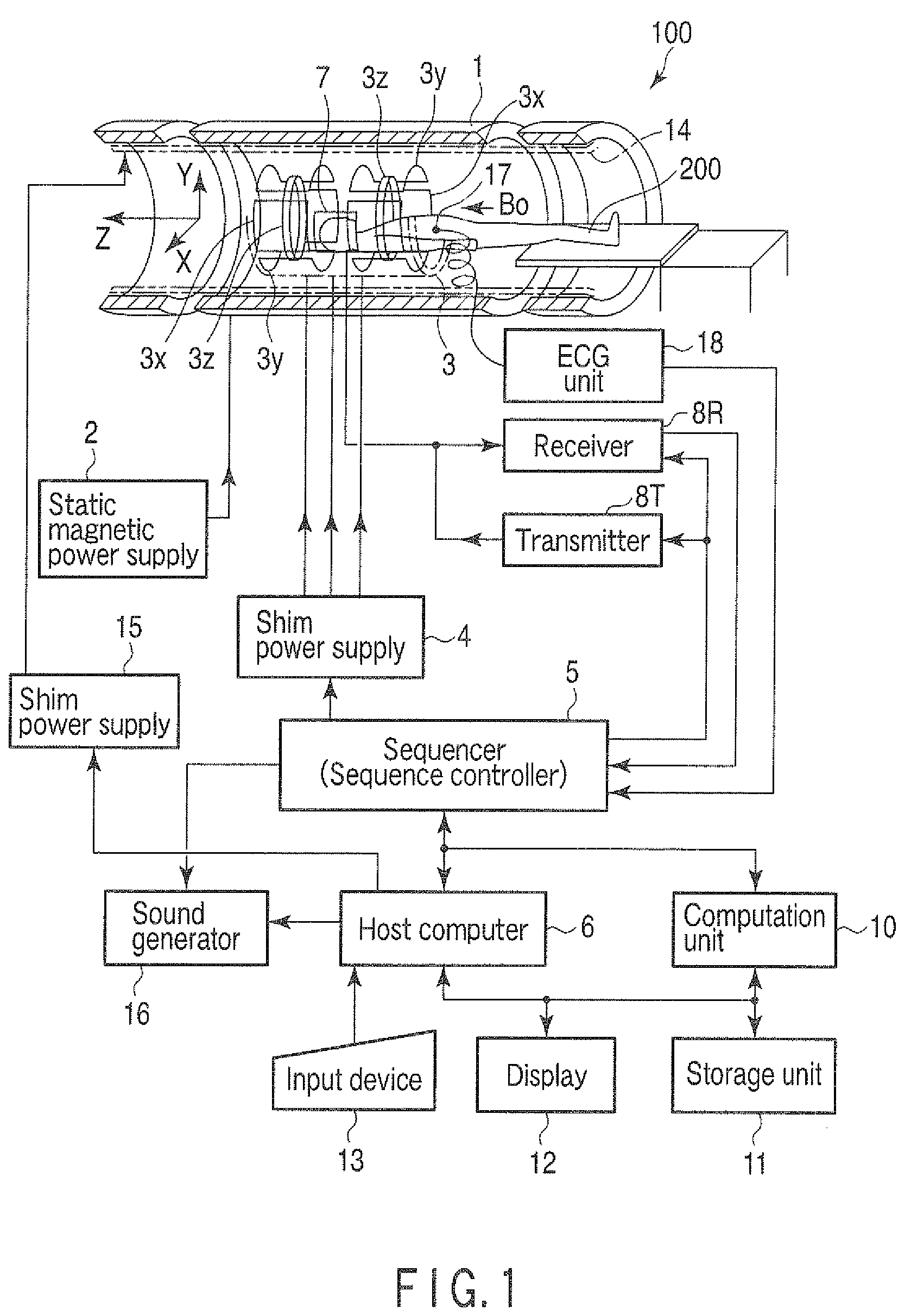
[0032]FIG. 1 is a view showing a structure of a magnetic resonance imaging apparatus (which will be referred to as an MRI apparatus hereinafter) 100 according to this embodiment.

[0033]This MRI apparatus 100 includes a bed unit on which a subject 200 is mounted, a static-magnetic-field generating unit that generates a static magnetic field, a gradient-magnetic-field generating unit that adds position information to the static magnetic field, a transmitting / receiving unit that transmits / receives a radio-frequency signal, and a control / computation unit that performs control over the entire system and image reconstruction. Further, the MRI apparatus 100 has a magnet 1, a static magnetic power supply 2, a gradient coil unit 3, a gradient power supply 4, a sequencer (a sequence controller) 5, a host computer 6, an RF coil unit 7, a transmitter 8T, a receiver...


PUM


Abstract

A magnetic resonance imaging apparatus includes an imaging unit which performs imaging more than once with respect to an imaging target while changing a central frequency of a fat suppression pulse, a generation unit which generates a plurality of images based on magnetic resonance signals obtained by imaging performed more than once, and a calculation unit which calculates factor information of spatial inhomogeneity of a fat suppression effect based on the plurality of images.

Description

CROSS-REFERENCE TO RELATED APPLICATIONS[0001]This application is based upon and claims the benefit of priority from prior Japanese Patent Application No. 2007-255704, filed Sep. 28, 2007, the entire contents of which are incorporated herein by reference.BACKGROUND OF THE INVENTION[0002]1. Field of the Invention[0003]The present invention relates to a magnetic resonance imaging apparatus that applies a fat suppression pulse to achieve suppression of a fat signal and an analysis method for a fat suppression effect in this magnetic resonance imaging apparatus.[0004]2. Description of the Related Art[0005]As a fat suppression method in magnetic resonance imaging, a chemical shift selective (CHESS) method or a spatial-spectral excitation pulse method is known.[0006]In any of these fat suppression methods, spatial inhomogeneity of a fat suppression effect occurs. As a method of improving spatial inhomogeneity of the fat suppression effect, there is so-called current shimming. In the curren...

Claims


Application Information

Patent Timeline
Patent Type & Authority Patents(United States)
IPC IPC(8): G01V3/00A61B5/055
CPCA61B5/0402A61B5/055A61B5/7285A61B5/318
Inventor KANAZAWA, HITOSHI
Owner TOSHIBA MEDICAL SYST CORP
Why Eureka
Try Eureka