
Magnetic resonance imaging apparatus and magnetic resonance imaging method

a magnetic resonance imaging and magnetic resonance imaging technology, applied in the field of nuclear magnetic resonance imaging, can solve the problems of unfavorable suppression of fatty signals, and achieve the effect of reducing imaging efficiency

Inactive Publication Date: 2010-06-24
HITACHI LTD
View PDF5 Cites 6 Cited by
  • Summary
  • Abstract
  • Description
  • Claims
  • Application Information

AI Technical Summary

Benefits of technology

[0013]According to the MRI apparatus and the MRI method of the present invention, the flip angle of the first sequence unit to be executed is controlled to be changed as a pulse sequence for suppressing a signal from specific atomic nucleus spins, whereby an even fat-suppressed image can be stably obtained without reduction of an imaging efficiency and also without being affected by unevenness of irradiation intensity of an RF pulse. Furthermore, even when the repetitive application time interval of the CHESS pulse is short, a homogenous fat-suppressed image can be stably obtained.

Problems solved by technology

However, the chess method has still have an unsolved problem that unevenness of suppression of the fatty signal would occur if the irradiation intensity is spatially uneven.

Method used


Image

  • Magnetic resonance imaging apparatus and magnetic resonance imaging method
  • Magnetic resonance imaging apparatus and magnetic resonance imaging method
  • Magnetic resonance imaging apparatus and magnetic resonance imaging method

Examples


first embodiment

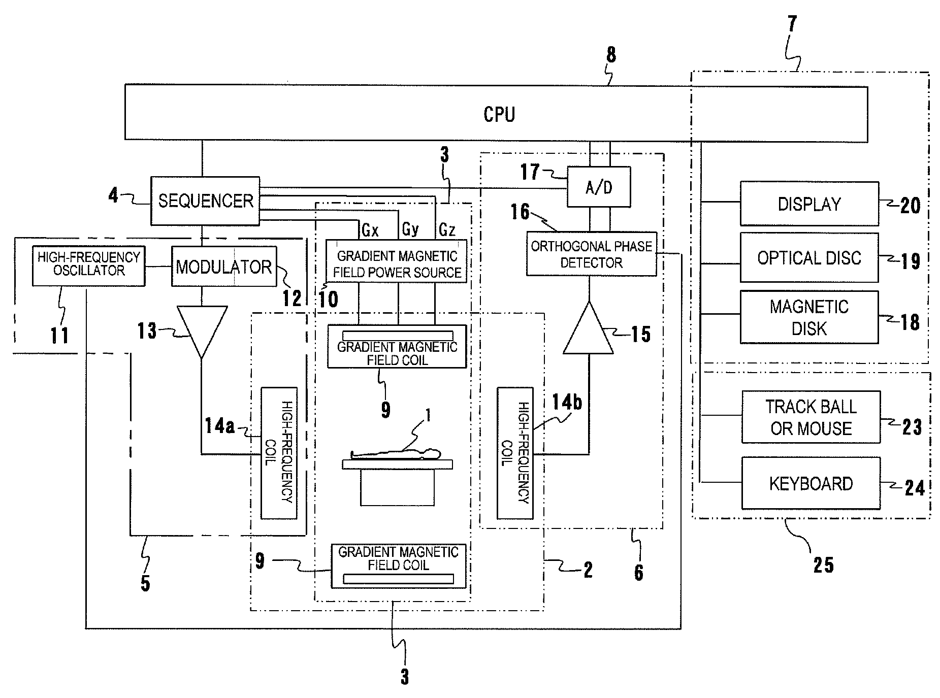
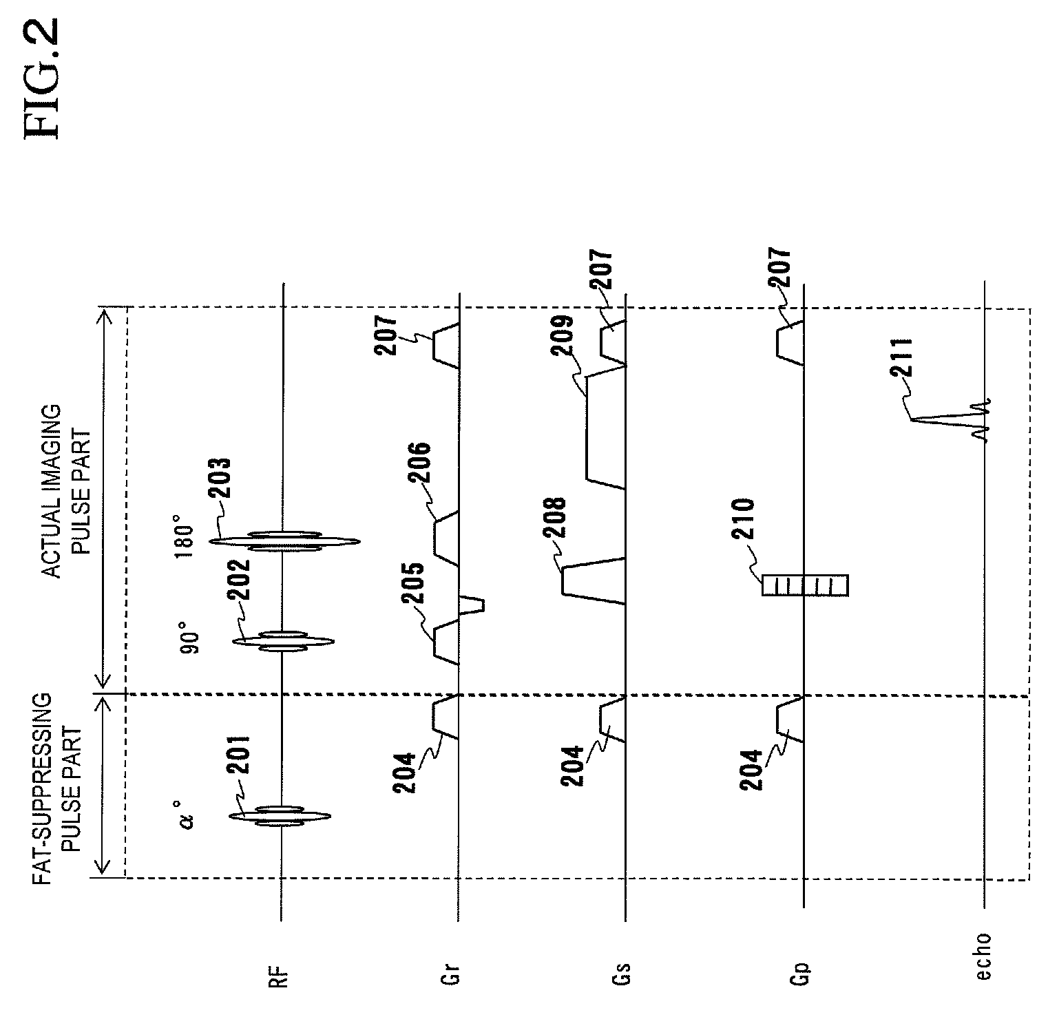
[0042]Next, a first embodiment of the MRI apparatus and the MRI method according to the present invention will be described. According to this embodiment, in the multi-slice imaging using the fat-suppressing imaging sequence in which the number of slices is set to 1 or more, the CHESS pulse is applied while the flip angle of the CHESS pulse is not fixed, but varied. Accordingly, a homogenous fat-suppressed image can be obtained even when the irradiation intensity of the RF pulse is uneven to some degree. The other portions are the same as the multi-slice imaging of FIG. 3. Therefore, the description of the same portions is omitted, and only different portions will be described hereunder with reference to FIG. 4.

[0043]FIG. 4 shows a sequence chart of multi-slice imaging using the fat-suppressing imaging sequence of this embodiment in which the number of slices is set to 1 or more. The sequencer 4 controls the fat-suppressing imaging on the basis of this sequence chart. In FIG. 4, onl...

second embodiment

[0067]Next, a second embodiment will be described. In this embodiment, the flip angle of the CHESS pulse is varied in segment measurement. That is, the K space is divided into plural segments, the actual imaging pulse part measures each echo signal belonging to plural segments, and the fat-suppressing pulse part applies CHESS pulses having different flip angles. Only the different points from the first embodiment described above will be hereunder described, the description of the same parts is omitted, and this embodiment will be described with reference to FIG. 8.

[0068]FIG. 8 shows the flip angle control of the CHESS pulse in the segment measurement of this embodiment.

[0069]FIG. 8(a) shows an example in which the K space is divided into segments of N (=3) in the phase encoded direction (ky direction). The center portion containing the origin of the K space (that is, a low area in the ky direction of the K space) is set to a segment 1 (Seg#1), and two areas at both the ends (that is...


PUM


Abstract

In order to stably obtain an even fat-suppressed image without reduction of an imaging efficiency and without being affected by unevenness of irradiation magnetic field of an RF pulse, when an imaging sequence having a first sequence part for suppressing a signal from a desired component of an examinee by applying a CHESS pulse and a second sequence part for measuring an echo signal from the examinee is repeated, the flip angle of the CHESS pulse is changed at plural times. In the case of multi-slice imaging, the flip angle of the CHESS pulse is changed in at lest two slice imaging.

Description

TECHNICAL FIELD[0001]The present invention relates to a nuclear magnetic resonance imaging (hereinafter referred to as “MRI”) apparatus and MRI method for measuring a nuclear magnetic resonance (hereinafter referred to as “NMR”) signal from hydrogen, phosphorus or the like in an examinee to image a density distribution of nucleus, a relaxation time distribution or the like, and particularly to a fat inhibiting technique using chemical shift.BACKGROUND ART[0002]When a biochemical tissue is placed in an even magnetic field space (B0, B0 direction is defined as z) in an MRI apparatus, the magnetic moments of atomic nucleus spins of tissue composing molecules make precession movement around the B0 direction at the natural resonance frequency of each spin. When these spins are exposed to a magnetic field (irradiated radio frequency magnetic field B1) having a frequency near to the resonance frequency from a direction perpendicular to the B0 direction, the net magnetic moment M is rotated...

Claims


Application Information

Patent Timeline
IPC IPC(8): G01R33/48
CPCA61B5/055G01R33/5607G01R33/4835G01R33/4828
Inventor ABE, TAKAYUKITAKEUCHI, HIROYUKITAKAHASHI, TETSUHIKO
Owner HITACHI LTD
Learn More