Surrounding image generating apparatus and method of adjusting metering for image pickup device

a technology of generating apparatus and generating apparatus, which is applied in the direction of television systems, instruments, transportation and packaging, etc., can solve the problems of providing an image with discomfort and poor visibility, difficult to combine images taken by multiple cameras in such a manner, and the difference in luminance cannot be shown, so as to eliminate discomfort or discomfort and improve the visibility of the area

Active Publication Date: 2010-02-16
ALPINE ELECTRONICS INC
View PDF29 Cites 30 Cited by
  • Summary
  • Abstract
  • Description
  • Claims
  • Application Information

AI Technical Summary

Benefits of technology

[0011]Accordingly, it is desirable to generate a surrounding image of the areas located around a vehicle, that a driver may view without discomfort or annoyance, with a smaller amount of calculation when the surrounding image is generated from images taken by multiple cameras mounted at different positions in the vehicle.
[0015]According to the present invention, the multiple images having the overlapping shooting areas in the focus / metering area have similar luminance values, so that breaks caused by the difference in luminance between the images can be almost hidden from view. The focus / metering area is set to an area where a driver should watch carefully, for example, the traveling direction of the vehicle or the direction where an obstacle exists. Consequently, it is possible to eliminate the annoyance or discomfort caused by the difference in luminance in the images in the traveling direction on which the driver should fix his / her eye during driving to improve the visibility of the areas at which the driver would look during driving. In addition, it is not necessary to perform complicated calculation, for example, calculation of a color for every pixel, thus generating a surrounding image around the vehicle without annoyance or discomfort for the driver with a smaller amount of calculation and / or processing required.

Problems solved by technology

When multiple images differing in the luminance are combined to generate a surrounding image showing the entire perimeter of the vehicle, there is a problem in that breaks caused by the difference in the luminance can be seen between the images in different directions to provide an image with discomfort and poor visibility.
It is difficult to combine the images taken by the multiple cameras in such a manner that any break caused by the difference in the luminance cannot be shown under various conditions differing in the position of the Sun, the weather, and the surrounding environment.
However, in the technology disclosed in Japanese Patent No. 3286306, there is a problem in that the color of the pixel corresponding to the point P cannot be appropriately adjusted to bring discomfort if the point P viewed from the virtual viewpoint is not associated with the images taken by the multiple cameras.
In addition, there is also a problem in that it takes a significant time to perform the calculation because the color of each pixel must be calculated.

Method used


Image

  • Surrounding image generating apparatus and method of adjusting metering for image pickup device
  • Surrounding image generating apparatus and method of adjusting metering for image pickup device
  • Surrounding image generating apparatus and method of adjusting metering for image pickup device

Examples


Embodiment Construction

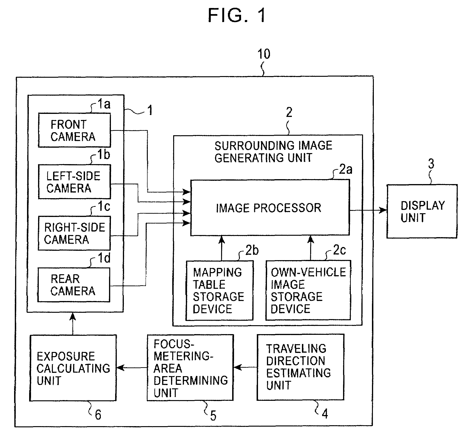
[0023]Embodiments of the present invention will now be described with the attached drawings. FIG. 1 is a block diagram showing an example of the structure of a surrounding image generating apparatus 10 for a vehicle, according to an embodiment of the present invention. Referring to FIG. 1, the surrounding image generating apparatus 10 includes a plurality of image pickup devices 1 including a front camera 1a taking an image ahead of the vehicle, a left-side camera 1b taking an image on the left side of the vehicle, a right-side camera 1c taking an image on the right side of the vehicle, and a rear camera 1d taking an image behind the vehicle.

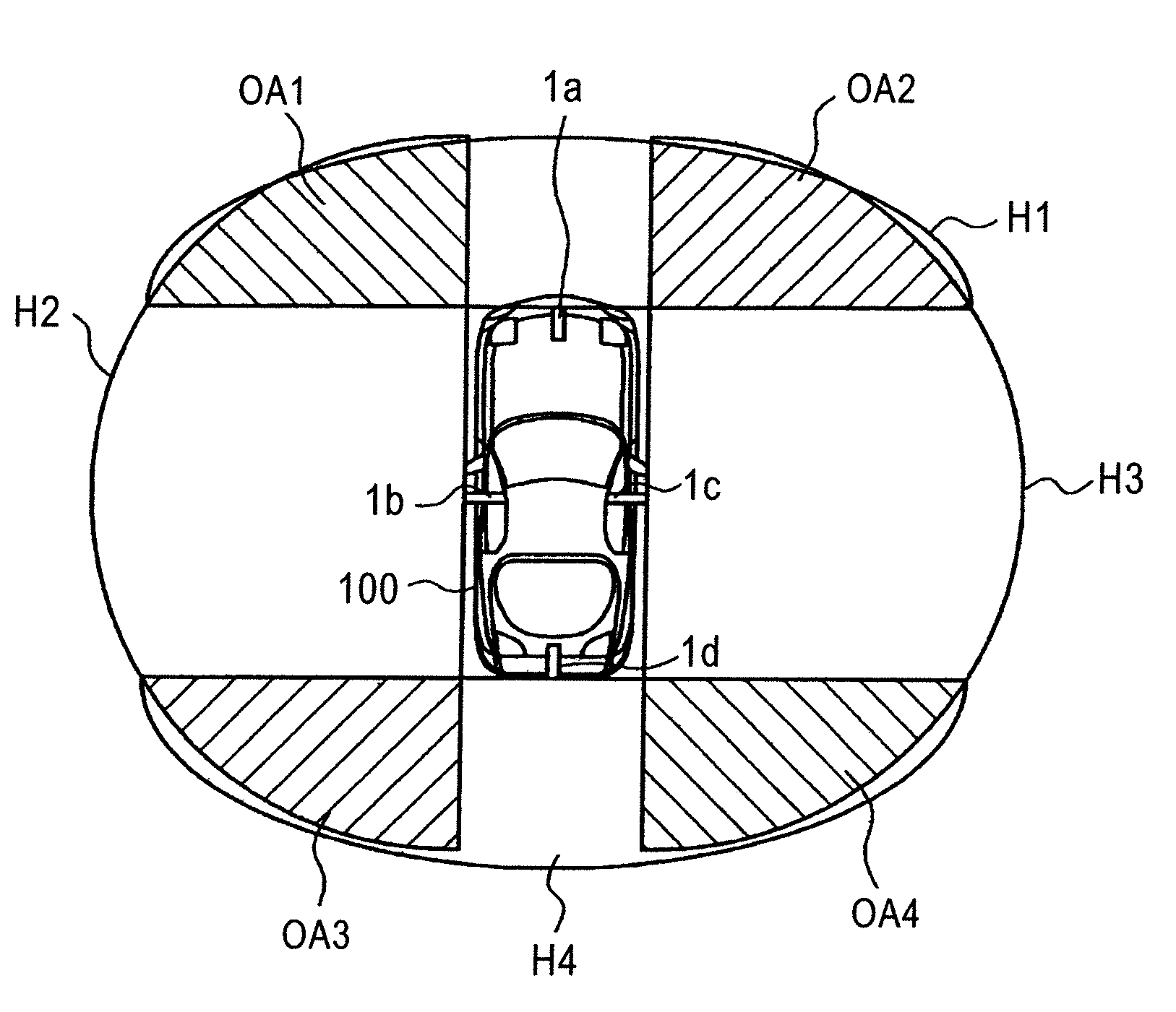
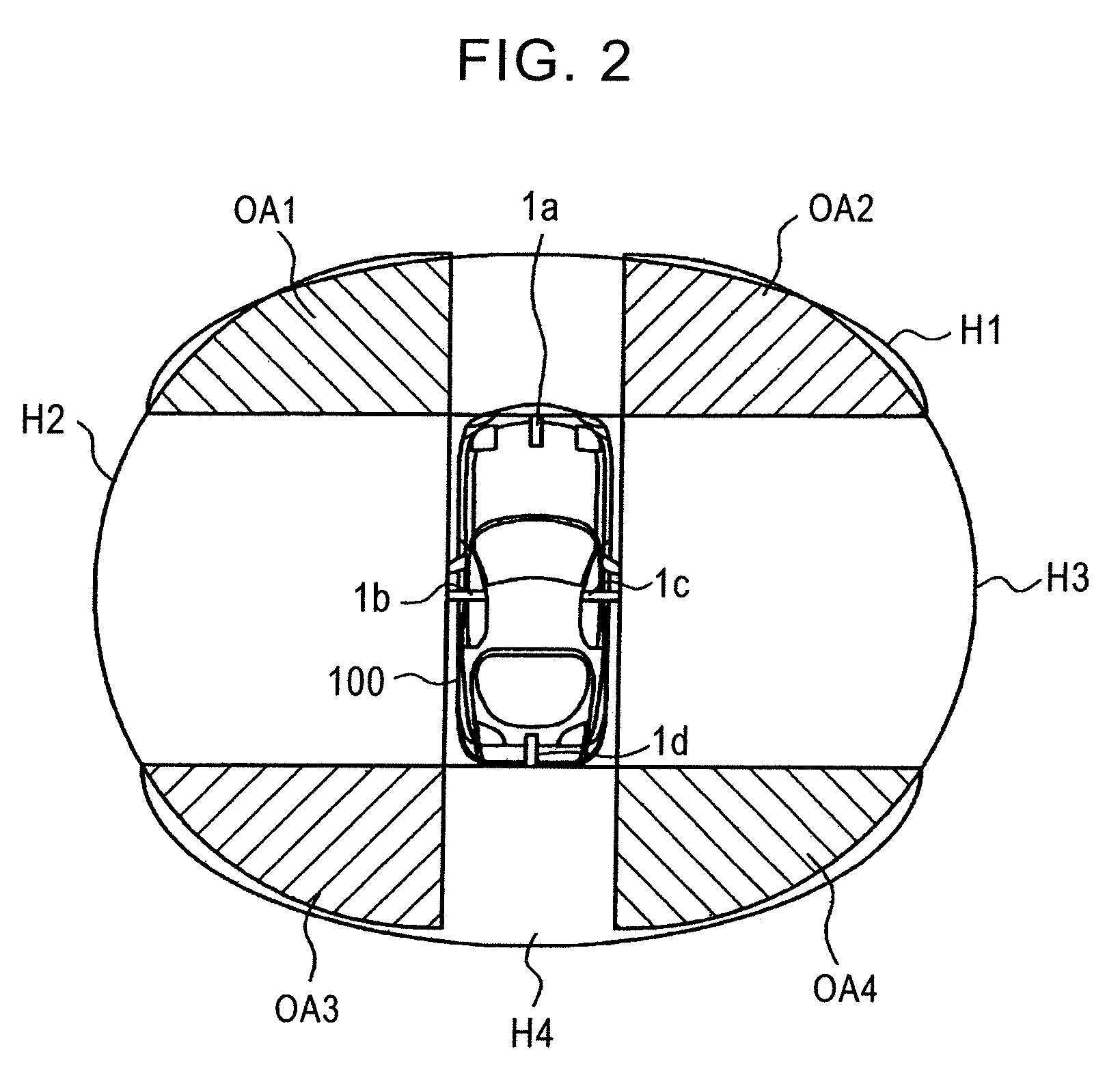
[0024]FIG. 2 shows arrangement of the front camera 1a, the left-side camera 1b, the right-side camera 1c, and the rear camera 1d and also illustrates examples of shooting areas. Referring to FIG. 2, the front camera 1a is mounted at the front of a vehicle 100 and takes an image of a front shooting area H1. The left-side camera 1b is mounted at t...


PUM


Abstract

A surrounding image generating apparatus changes a viewpoint of images around a vehicle, taken by multiple image pickup devices mounted at different positions along the vehicle, to generate a surrounding image of the areas around the vehicle viewed from a virtual viewpoint located above the vehicle. The surrounding image generating apparatus includes a metering area determining unit determining at least one overlapping area in which the shooting areas of the image pickup devices are overlapped with each other to be a metering area for at least part of the image pickup devices; an exposure calculating unit focusing metering on the metering area for the at least part of the image pickup devices to calculate an appropriate exposure of each of the image pickup devices; and a surrounding image generating unit generating the surrounding image by using image signals generated in accordance with the calculated exposures.

Description

RELATED APPLICATIONS[0001]The present application claims priority to Japanese Patent Application Serial Number 2006-137393, filed on May 17, 2006, the entirety of which is hereby incorporated by reference.BACKGROUND OF THE INVENTION[0002]1. Field of the Invention[0003]The present invention relates to surrounding image generating apparatuses and methods of adjusting metering for image pickup devices. Particularly, the present invention is preferably applied to a surrounding image generating apparatus that generates a surrounding image of a plurality of areas located around a vehicle, viewed from a virtual viewpoint located above the vehicle, and to a method of adjusting metering for multiple image pickup devices that are mounted along the perimeter of a vehicle to take images of the plurality of areas located around the vehicle.[0004]2. Description of the Related Art[0005]Hitherto, technologies are proposed in which multiple cameras are mounted along the perimeters of vehicles and im...

Claims


Application Information

Patent Timeline
Patent Type & Authority Patents(United States)
IPC IPC(8): B60Q1/00
CPCB60Q9/005B60R1/00H04N7/181B60R2300/102B60R2300/105B60R2300/302B60R2300/303B60R2300/305B60R2300/8093
Inventor WATANABE, HISAYUKINOMURA, TSUBASA
Owner ALPINE ELECTRONICS INC
Why Eureka
Try Eureka