Shock absorbing device for brake pedals

a technology brake pedal, which is applied in the field of shock absorption device of brake pedal, can solve the problems of insufficient shock absorption effect, complex structure of the brake pedal, and severe injury to the driver, and achieve the effect of reducing the speed of the collision of the driver's leg and minimizing the injury to the driver

Active Publication Date: 2010-02-23
HYUNDAI MOTOR CO LTD
View PDF12 Cites 12 Cited by
  • Summary
  • Abstract
  • Description
  • Claims
  • Application Information

AI Technical Summary

Benefits of technology

[0007]Embodiments of the present invention provide a shock absorbing device of a brake pedal which has a structure such that, when a frontal vehicle collision occurs, the brake pedal rotates in a forward direction of the vehicle, that is, in a direction moving away from a driver, thus reducing the speed of the collision of the driver's leg with the brake pedal, thereby minimizing injury to the driver.
[0011]The guide means has an elliptical guide hole to limit moving distance of the hinge shaft in the vehicle collision.

Problems solved by technology

However, in the conventional brake system having the above-mentioned construction, if the vehicle, while traveling, frontally collides, the brake pedal supported underneath the dash panel is rotated towards the driver, so that the leg of the driver may strike the brake pedal, thus resulting in a severe injury to the driver.
To reduce injury to the driver due to the brake pedal in a vehicle frontal collision, various shock absorbing devices for brake pedals have been developed, but they have problems in that the structures thereof are complex or shock absorbing effect thereof is insufficient.

Method used


Image

  • Shock absorbing device for brake pedals
  • Shock absorbing device for brake pedals
  • Shock absorbing device for brake pedals

Examples


Embodiment Construction

[0030]Hereinafter, an embodiment of the present invention will be described in detail with reference to the attached drawings.

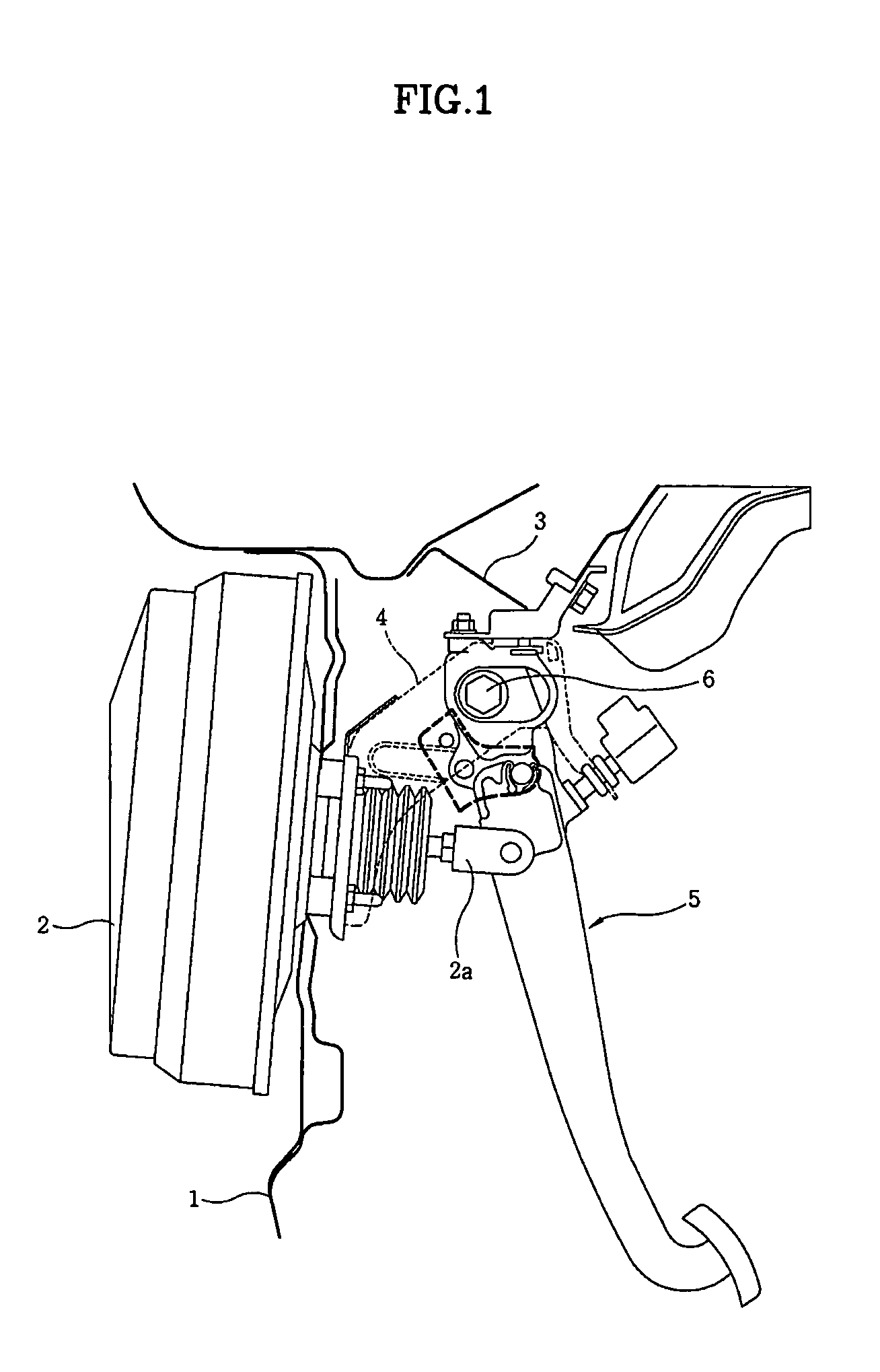
[0031]FIG. 1 shows a brake pedal 5 provided with a shock absorbing device according to the embodiment of the present invention. Referring to FIG. 1, a brake booster 2 is mounted to a dash panel 1. The brake pedal 5 is mounted to a mounting bracket 4, fastened to a vehicle body 3, so as to be rotatable around a hinge shaft 6 in forward and rearward directions with respect to the vehicle body 3. Furthermore, a push rod 2a of the brake booster 2 is coupled to the brake pedal 5.

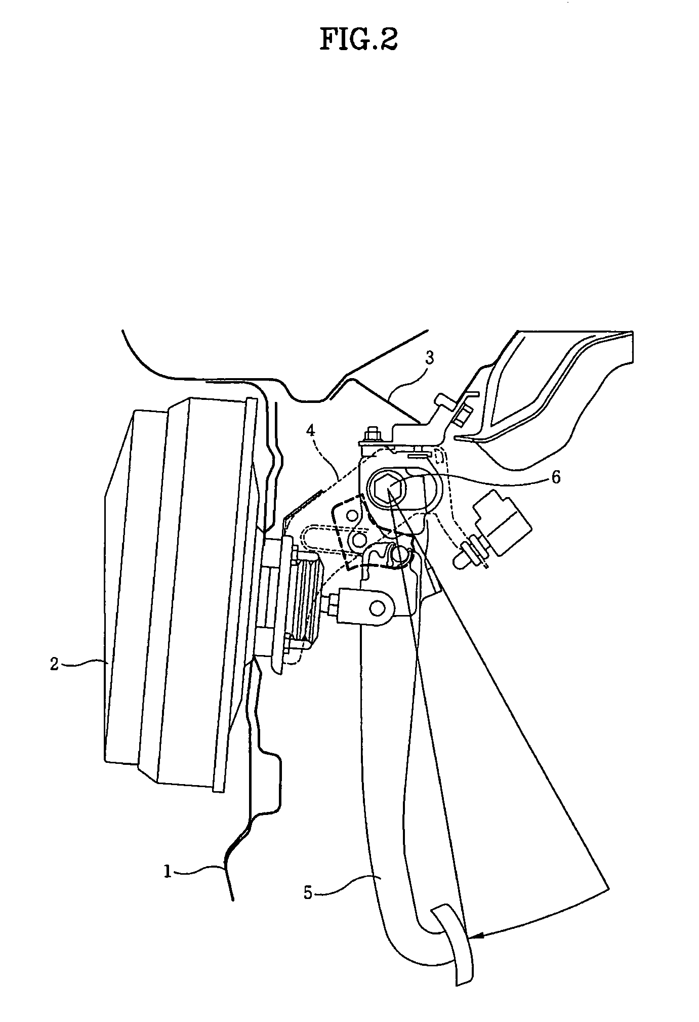
[0032]When a driver manipulates the brake pedal 5, the brake pedal 5 is rotated in a forward direction of the vehicle body 3, as shown in FIG. 2. Then, the push rod 2a of the brake booster 2 is pushed forwards by the brake pedal 5, so that the brake booster 2 amplifies actuating force of the brake pedal 5 generated by the driver.

[0033]FIG. 3 shows the brake pedal 5 rotated in a forward dir...


PUM


Abstract

A shock absorbing device includes a mounting bracket which is fastened at a first end thereof to the vehicle body and removably mounted at a second end thereof to the vehicle body, an upper pedal arm which is rotatably mounted to the mounting bracket using a hinge shaft, and a lower pedal arm which is removably coupled to the upper pedal arm using a locking pin. The shock absorbing device further includes a locking pin removal device which removes the lower pedal arm from the upper pedal arm when a vehicle collision occurs, and a guide device which serves as a guide for movement of the mounting bracket when the vehicle collision occurs and provides a reaction force for the locking pin removal device.

Description

CROSS-REFERENCE TO RELATED APPLICATIONS[0001]The present application is based on, and claims priority from, Korean Application Serial Number 10-2005-0108172, filed on Nov. 11, 2005, the disclosure of which is hereby incorporated by reference herein in its entirety.FIELD OF THE INVENTION[0002]The present invention relates to brake pedals for vehicles and, more particularly, to an shock absorbing device for a brake pedal which has a structure such that, when a frontal vehicle collision occurs, the brake pedal rotates in a forward direction of the vehicle, thus minimizing injury to the leg of a driver resulting from impact with the brake pedal.BACKGROUND OF THE INVENTION[0003]As well known to those skilled in the art, a brake system is provided in a vehicle to reduce the speed of the vehicle or to stop it. The brake system includes a brake pedal which is disposed near a driver, a brake booster which amplifies actuating force of the brake pedal, a master cylinder which generates hydraul...

Claims


Application Information

Patent Timeline
Patent Type & Authority Patents(United States)
IPC IPC(8): G05G1/30B60K28/10B60T7/06
CPCB60R21/09B60T7/065G05G1/327Y10T74/20888Y10T74/20528B60T7/06
Inventor PARK, DAE-DEUG
Owner HYUNDAI MOTOR CO LTD
Why Eureka
Try Eureka