Illumination device for an indicating needle

a technology of illumination device and indicating needle, which is applied in the direction of instruments, machines/engines, transportation and packaging, etc., can solve the problems of large losses and drawbacks of conventional illumination devices, and achieve the effects of reducing the variations in improving visibility and external appearance, and reducing the variation of the brightness of the needle body

Inactive Publication Date: 2010-02-23
YAZAKI CORP
View PDF4 Cites 14 Cited by
  • Summary
  • Abstract
  • Description
  • Claims
  • Application Information

AI Technical Summary

Benefits of technology

[0016]In view of the above-identified drawbacks, the purpose of the present invention is to provide an illumination device for an indicating needle that can reduce variations in brightness of the indicating needle when the indicating needle turns and achieve improved visibility of illumination and improved quality of external appearance.
[0019]With the above construction and arrangement, the luminance control unit controls the luminance of the light sources in response to the turning of the indicating needle such that the luminance is lowest when the light emitted along the axis of the light source is reflected at the region of the reflection surface which the longitudinal central line of the needle body intersects with, and the luminance becomes larger as the position of reflection of the light from the axis of the light source on the reflection surface moves away from the region of the reflection surface which the above-defined longitudinal central line intersects with. Accordingly, the amount of light emitted by the light source and incident on a region that is not seriously affected by losses can be made constant during travel to the needle body via the reflection surface even when the indicating needle turns, thus reducing the variations in brightness of the needle body while turning and ensuring improved visibility and external appearance.

Problems solved by technology

Such conventional illumination devices have drawbacks.
Understandably, larger losses will result due to the increased number of times of reflection.

Method used


Image

  • Illumination device for an indicating needle
  • Illumination device for an indicating needle
  • Illumination device for an indicating needle

Examples


Embodiment Construction

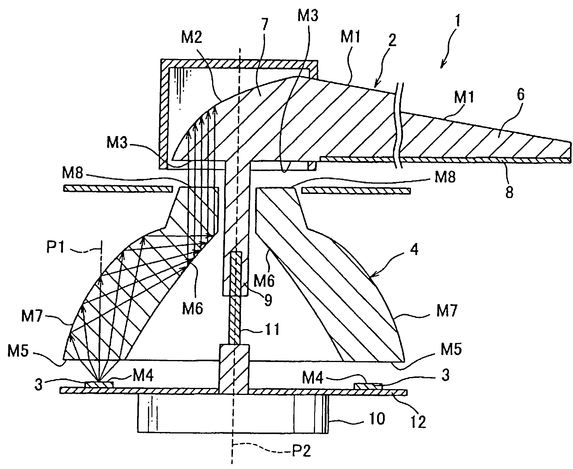
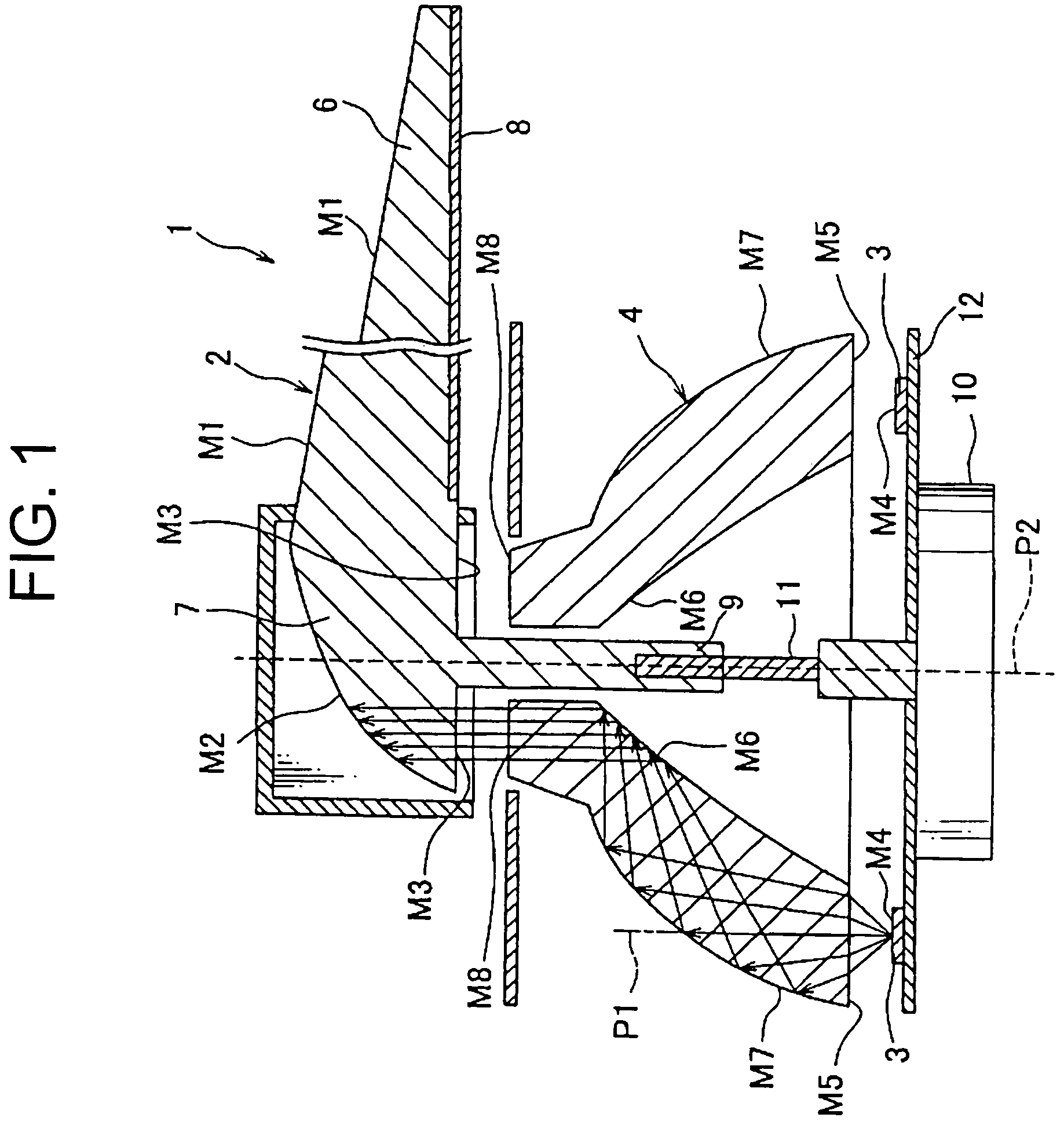
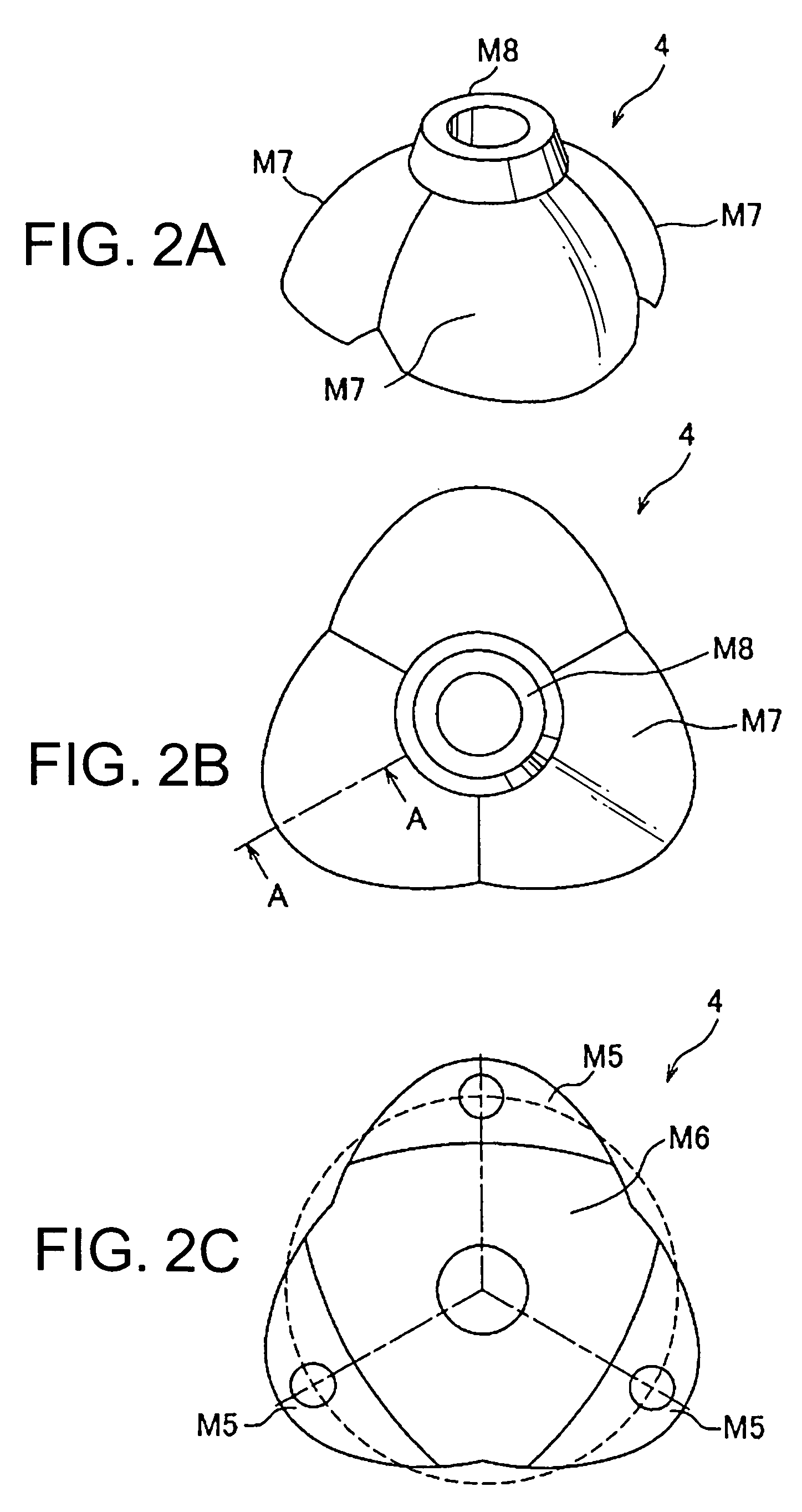
[0034]An illumination device 1 for an indicating needle according to one embodiment of the present invention is described below with reference to the attached drawings. Referring to FIG. 1, the illumination device 1 includes an indicating needle 2, a light source 3, a light-guiding member 4, and an illumination device controller 5 (see FIG. 4).

[0035]The indicating needle 2 is made of optically transparent resin such as polymethylmethacrylate (PMMA) and polycarbonate (PC). The indicating needle 2 includes a needle body 6 and a needle base 7.

[0036]The needle body 6 is formed in a shape of a rod that points an indication provided for example upon a speedometer dial or a tachometer dial. A reflection surface M1 is provided on a front surface of the needle body 6. An injection-molded layer 8 is provided on a rear surface of the needle body 6. Note that the front surface is a portion that a driver who takes a driver's seat can see while driving, and the rear surface a portion that in norm...


PUM


Abstract

An illumination device for an indicating needle includes a plurality of light sources, an indicating needle, a guiding member, and a luminance control unit. The indicating needle includes a needle body and a needle base. The base has an entrance surface and a reflection surface. A luminance control unit controls luminance of the light sources in response to turning of the indicating needle such that the luminance is lowest when a light emitted perpendicularly from a center of an emitting surface of the light source is reflected off a reflection surface's region which a longitudinal central line of the needle body intersects with, and that the luminance gradually increases as the light emitted by the light source from the center of the emitting surface thereof is reflected off a region that is more distant from the region which the longitudinal central line of the needle body intersects with.

Description

CROSS REFERENCE TO RELATED APPLICATION[0001]The priority application Japanese Patent Application No. 2007-320549 upon which the present patent application is based is hereby incorporated by reference.BACKGROUND OF THE INVENTION[0002]1. Field of the Invention[0003]The present invention generally relates to an illumination device for an indicating needle. More particularly, the present invention relates to an illumination device for an indicating needle that includes (a) an indicating needle that has a needle body framed in a shape of a rod and configured to point indications, and a needle base having a reflection surface configured to reflect a light entering an inside of the needle base via an entrance surface thereof toward a pointed end (or a tip) of the needle body, a width of the needle base being wider than that of the needle body, and (b) light sources that are arranged around a driving shaft of the indicating needle and each configured to emit the light that enters the inside...

Claims


Application Information

Patent Timeline
Patent Type & Authority Patents(United States)
IPC IPC(8): G01D11/28
CPCG01D11/28G01D13/265B60K2370/336B60K2370/6992
Inventor HARADA, TAKESHIOGAWA, MASAYUKIFURUYA, YOSHIYUKI
Owner YAZAKI CORP
Why Eureka
Try Eureka