Infrared thermometer

a technology of infrared thermometers and thermometers, which is applied in the direction of heat measurement, optical radiation measurement, instruments, etc., can solve the problems of unavoidable inaccuracy of readings, electronic thermometers require complex and complicated disinfection processes, and electronic thermometers have relatively strict requirements regarding accuracy and other issues to achieve the effect of improving stability, less deviation, and more accurate temperature measuremen

Inactive Publication Date: 2010-02-23
ACTHERM INC
View PDF40 Cites 5 Cited by
  • Summary
  • Abstract
  • Description
  • Claims
  • Application Information

AI Technical Summary

Benefits of technology

[0008]Thus, it is one objective of the present invention to provide an infrared thermometer for ear or skin temperature that implements the heat dissipation means to cool the infrared sensor, so as to provide relatively more accurate temperature measurement.
[0009]It is another objective of the present invention to provide an infrared thermometer for ear or skin temperature that implements the heat dissipation means to cool the infrared sensor, so as to permit of temperature measurement with improved stability and less deviation during continuous use.
[0010]It is yet another objective of the present invention to provide a method for manufacturing an infrared thermometer for ear or skin temperature that implements the heat dissipation means to cool the infrared sensor, so as to provide relatively more accurate temperature measurement.
[0011]It is still another objective of the present invention to provide a method for manufacturing an infrared thermometer for ear or skin temperature that implements the heat dissipation means to cool the infrared sensor, so as to permit of temperature measurement with improved stability and less deviation during continuous use.

Problems solved by technology

On the other hand, as an electronic thermometer determines the final temperature reading at thermal equilibrium by acquiring a minimum temperature variation during a period of time which is shorter than the measuring time of a mercury-in-glass thermometer, a certain level of inaccuracy of the reading is unavoidable.
Besides, an electronic thermometer requires complex and complicated disinfection process after use, so as to be reapplied without hygiene concern.
Further, an electronic thermometer has relatively stricter requirements regarding to electric circuits while it requires an inconvenient stability check for measurement circuit.
In addition to its relatively lower precision, the electronic thermometer may be clumsy in measuring temperature when pool connection of its sensor circuits occurs.
However, the aforementioned conventional infrared ear thermometer still has some drawbacks.
However, when such an infrared ear thermometer is put into clinical practice, the thermopile sensor is subject to the interference of the body temperature around the human ear canal.
As a result, the accuracy of temperature measurement can be desirably affected.
Nevertheless, such a prior-art heat dissipation means that ensures the constant temperature of the infrared sensor against interference can only work efficiently for a short period of use of the infrared ear thermometer.
In the case that the infrared ear thermometer is continuously used, since the human body heat accumulated in the metal blocks cannot be dissipated, it eventually affects the constant temperature of the infrared sensor, and, as a result, the degenerate accuracy of temperature measurement is caused.

Method used


Image

  • Infrared thermometer
  • Infrared thermometer
  • Infrared thermometer

Examples


second embodiment

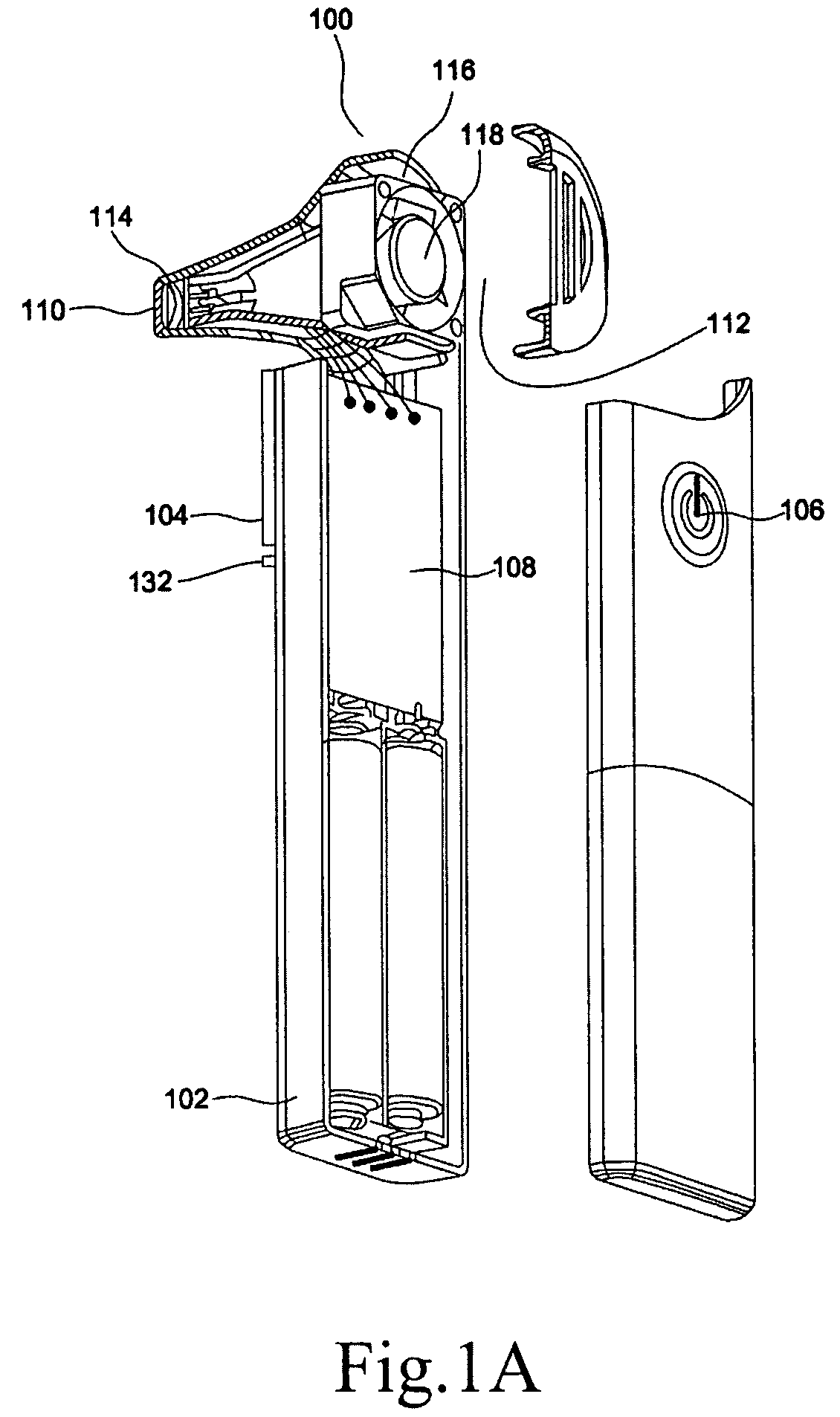
[0026]In the present invention, a method for manufacturing an infrared ear thermometer is disclosed and comprising the following steps:

[0027](1) Providing a body 100 which comprises a housing 102, a display 104, a power switch 106, a control circuit 108, a protrudent first opening 110 and a second opening 112;

[0028](2) Providing an infrared sensor 114, which is provided inside the body and near the first opening 110 wherein the infrared sensor 114 comprises a thermopile 124, a color filter 126, a metal cap 128 and a thermistor 130; and

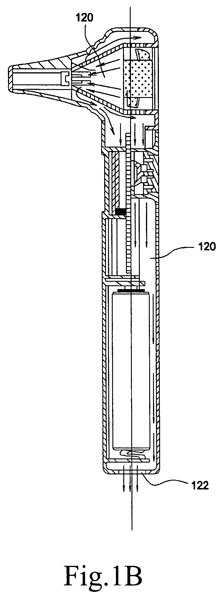
[0029](3) Providing a heat dissipation means 116, which is provided inside the body and near the second opening 112.

first embodiment

[0030]In the present embodiment, the novel features of the body 100, the infrared sensor 114 and the heat dissipation means 116 are the same as those described in the

third embodiment

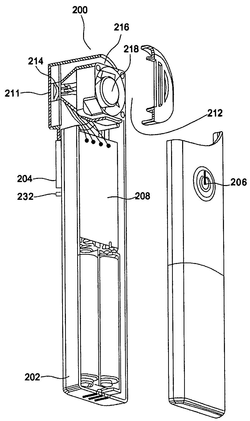
[0031]Please see FIGS. 2A, 2B, and 2C, wherein an infrared thermometer according to the present invention is depicted.

[0032]The disclosed infrared thermometer 200 comprises a body, an infrared sensor 214 and a heat dissipation means 216.

[0033]The body comprises a housing 202, a display 204, a power switch 206, a control circuit 208, a first opening 211 and a second opening 212. The infrared sensor 214 is positioned near the first opening 211 in the body while the heat dissipation means 216 is deposited near the second opening 212 in the body. The infrared sensor 214 comprises a thermopile 224, a color filter 226, a metal cap 228 and a thermistor 230, wherein the thermopile 224 is composed of a plurality of coupled thermal couples. The thermistor 230 may be installed inside the thermopile 224, or, alternatively, installed outside the thermopile 224. The power switch 206 is provided for starting or shutting the power source of the infrared thermometer 200 and may be selected from a gr...


PUM

PropertyMeasurementUnit
temperatureaaaaaaaaaa
body temperatureaaaaaaaaaa
stabilityaaaaaaaaaa

Abstract

This invention discloses an infrared thermometer for ear or skin temperature. The infrared thermometer comprises a body, an infrared sensing element, and a heat dissipating means. The heat dissipation means is provided behind or below the infrared sensing element for urging the air flowing in and out of the body, so as to contribute better heat dissipation and air circulation around the infrared sensing element. Hence the accuracy and stability of the infrared thermometer are improved.

Description

BACKGROUND OF THE INVENTION[0001]1. Technical Field[0002]This invention discloses a device for measuring temperature, and more particularly, refers to a device that uses an infrared sensor to measure temperature.[0003]2. Description of Related Art[0004]Mercury-in-glass thermometers and electronic thermometers are popularly used for measuring body temperature. A mercury-in-glass thermometer functions based on the principle of conductive thermal equilibrium and therefore requires more time for measuring temperature. Since mercury is pollutant and seriously harmful to human bodies, it has been gradually eliminated from the market in recent years. On the other hand, as an electronic thermometer determines the final temperature reading at thermal equilibrium by acquiring a minimum temperature variation during a period of time which is shorter than the measuring time of a mercury-in-glass thermometer, a certain level of inaccuracy of the reading is unavoidable. Besides, an electronic ther...

Claims


Application Information

Patent Timeline
Patent Type & Authority Patents(United States)
IPC IPC(8): G01J5/02G01K1/02G01J5/03
CPCG01J5/0003G01J5/0011G01J5/061G01J5/049G01J5/026Y10T29/49002G01J2005/068G01J5/028G01J5/064
Inventor HSIEH, CHIH-WEI
Owner ACTHERM INC
Why Eureka
Try Eureka